DCC
|
Índex
|
|
|
|
|
|
Marca / Brand
|
Comandament / Throttle |
Estació
de control / Command station |
Booster
|
Decoder |
Retorn / Feedback
|
bucle / loop |
info
|
|
|
software |
app
/ PC interface |
hardware |
|
|
mobile |
stationary |
bidirectional
|
detecció / detection |
|
|
Bus
|
|
|
|
|
|
|
|
|
|
|
|
|
|
|
|
|
|
|
|
decoder
|
sensor
|
current
|
|
|
|
|
|
|
|
|
|
|
|
|
controller
|
programming
|
reed sensor |
controller
|
sensor
|
|
|
Open
|
(altres/other) |
|
|
|
|
|
|
|
|
|
|
|
|
|
|
|
Arduino
based
|
|
|
|
|
|
|
|
|
|
|
|
|
|
|
|
| MERG |
|
|
|
|
|
|
|
|
|
|
|
|
|
|
|
| OpenDCC |
|
|
|
|
|
|
|
|
|
|
|
|
|
|
|
| Paco Cañada (digitrens) |
|
|
|
|
|
|
|
|
|
|
|
|
|
|
|
Commercial
|
(altres/other)
|
|
|
|
|
|
|
|
|
|
|
|
|
|
|
|
| YaMoRC |
|
|
|
- YD7110 (integrated)
- YD7001-E
(intermediate)
|
|
|
|
RailCom SENSOR:
|
OPTO SENSOR:
|
ES-PGM-LINK, ES-OUT-LINK:
|
|
Current SENSOR:
Ground SENSOR:
|
|
|
|
Digikeijs
|
|
|
|
|
|
|
|
|
|
|
|
|
|
|
|
|
|
|
|
|
|
|
|
|
|
|
|
|
|
| Fleischmann
/ Roco |
Android:
|
|
|
- 680801
- Roco/Fleischmann multiMAUS (as master)
- z21 (white)
- Z21 (black)
|
- 10761 (2.5A) (no shortcut protection)
- 10764
(3.2A, master, slave, booster out)
- 10765
(3.2A, booster in/out) / 10762
- 10779
- 670601
transformer (79€)
- Z21 Light Booster (10805) (RailCom) (B-BUS)
(3A) (auto inversion) (99€) (89,99€)
(99,99€)
- Z21 Single Booster (10806)
(CAN, B-BUS, CDE) (3A) (154€)
- Z21 Dual Booster (10807)
(CAN, B-BUS, CDE) (2x3A)(234€)
- Roco
10765 Digital booster (B-BUS)
(replaced by Z21 Booster light)
- 10789
- Z21®-Booster Adapter (CDE boosters)
|
|
|
|
|
|
|
|
|
Lenz
|
|
- LI100 (XpressNet-RS232)
- LI100F (XpressNet-RS232)
- LI101F
- LI-USB
(XpressNet-USB)
- LI-USB-Ethernet
(XpressNet-USB, Ethernet)
|
|
|
|
|
|
- Lenz LRC100
- Lenz LRC120 (screen: loco
address)
|
|
|
|
|
|
|
|
| Märklin / Minitrix |
|
|
|
|
|
|
|
|
|
|
|
|
|
|
|
Oscilloscopio
|
|
|
|
|
|
|
|
|
|
|
|
|
|
|
|
| Rocrail |
Rocrail server + :
|
|
|
|
|
|
|
|
RocRail
feedback:
- GCA93: current
- GCA133: IR
- GCA173 Hall-sensor
|
|
|
|
|
|
|
|
|
|
-
dispositiu / device
|
cab
bus
|
central
|
control
bus
|
dispositiu / device
|
- throttle
- ordinador / computer
|
|
command
station |
|
- descodificadors estàtics (accessoris) / static
decoders (accessories)
- descodificadors mòbils (locomotores) / mobile
decoders (locomotive)
|
|
feedback
bus
|
- mòduls de retroalimentació / feedback modules
|
|
- Control
bus
- Cab
buses / Throttle
network (allow loco controllers connect to command
station)
- CAN Bus (by Zimo)
- LocoNet
- Loconet
(iGwiki)
- LocoNet
Personal Use Edition 1.0 Specification (pdf)
-
| length |
opcode |
byte 1 |
byte 2 |
byte 3 |
byte 4 |
byte 5 |
byte 6 |
| 2 bytes |
OPC_IDLE |
0x85 |
CKSUM |
|
|
|
|
| OPC_GPON |
0x83 |
CKSUM |
|
|
|
|
| OPC_GPOFF |
0x82 |
CKSUM |
|
|
|
|
| OPC_BUSY |
0x81 |
CKSUM |
|
|
|
|
| 4 bytes |
OPC_LOCO_ADR |
0xBF |
0x00 |
ADR |
CHK |
|
|
| OPC_SW_ACK |
0xBD |
SW1 |
SW2 |
CHK |
|
|
| OPC_SW_STATE |
0xBC |
SW1 |
SW2 |
CHK |
|
|
| OPC_RQ_SL_DATA |
0xBB |
SLOT |
0 |
CHK |
|
|
| OPC_MOVE_SLOTS |
0xBA |
SRC |
DEST |
CHK |
|
|
| OPC_LINK_SLOTS |
0xB9 |
SL1 |
SL2 |
CHK |
|
|
| OPC_UNLINK_SLOTS |
0xB8 |
SL1 |
SL2 |
CHK |
|
|
| OPC_CONSIST_FUNC |
0xB6 |
SLOT |
DIRF |
CHK |
|
|
| OPC_SLOT_STAT1 |
0XB5 |
SLOT |
STAT1 |
CHK |
|
|
| OPC_LONG_ACK |
0xB4 |
LOPC |
ACK1 |
CHK |
|
|
| OPC_INPUT_REP |
0xB2 |
IN1 |
IN2 |
CHK |
|
|
| OPC_SW_REP |
0xB1 |
SN1 |
SN2 |
CHK |
|
|
| OPC_SW_REQ |
0xB0 |
SW1:
<0,A6,A5,A4 - A3,A2,A1,A0>
(7 LS address bits) |
SW2:
<0,0,DIR,ON - A10,A9,A8,A7>
(DIR=1 for closed/green, =0 for thrown/red
ON=1 for output ON, =0 for output OFF) |
CHK |
|
|
| 6 bytes |
(reserved) |
OPC |
ARG1 |
ARG2 |
ARG3 |
ARG4 |
CKSUM |
| variable bytes |
... |
|
|
|
|
|
|
- XPressNet (X-BUS)
- Bus
de retorn / Feedback bus
|
|
|
- Digital
Command Control (wp)
- Modes
-
mode
|
z21
LED |
Normes
NMRA
|
Operations |
Programming |
| Decoder
programming (on z21)
|
programming mode |
escriptura CV |
lectura CV |
Mode
d'operacions /
Operations mode
|
blau |
NMRA
S 9.2.1
|
- control de locomotores (descodificador mòbil)
- velocitat
- funcions (F0...F...): llums, sons, ...
- control d'accessoris (descodificador fix)
- control de desviaments
- control de senyalització
- ...
|
Operations
mode programming / Program on main
- POM
- hi pot haver diversos descodificadors
connectats, perquè
- s'envia a una adreça en concret
- pot llegir valors de CV només si Railcom està activat
- Exemples:
|
|
|
|
Mode
de servei /
Service mode
|
verd |
NMRA
S 9.2.3 |
- |
Service
mode / Broadcast programming / Programming
track - PT
- només hi pot haver un descodificador connectat
(per això habitualment es fa servir un tram
de via aïllat), perquè
- s'envia per broadcast (a cap adreça en
concret)
- pot llegir valors de CV, fent servir petits
consums elèctrics (DCC
ACK)
- alguns descodificadors estàtics, per
exemple DR4018,
necessiten a més una resistència i el led
PROGRAM encès
- es fa servir per a programar l'adreça de la
locomotora
|
- direct byte
- direct bit
- paged
- register
|
|
|
- Estructura / Structure
- NEM 671,
NMRA
- Monitoratge
- Bits
- Formats de paquets
- NMRA
S
9.2.1: Operations
mode
12-bit
|
|
byte
|
[byte]
|
[byte]
|
[byte] |
byte
|
programari
/ software
|
| preamble |
address
(pDccMsg->Data[0])
|
CCC
|
DDDDD
|
[DDDDDDDD]
|
[DDDDDDDD] |
[DDDDDDDD] |
error
correction |
NmraDcc
|
| 111111111111 |
00000000
(0)
|
broadcast
|
00000000 |
|
00000001-01111111
(1-127)
|
multi-function
(7-bit) |
0AAAAAAA
|
|
11000000-11100111
(192-231)
|
multi-function
(14-bit) |
11AAAAAA
|
AAAAAAAA
|
|
000
|
Decoder
and Consist Control Instruction
|
0
|
Decoder Control
...
|
|
|
|
EEEEEEEE |
execDccProcessor():
pDccMsg->Data[0] < 128
|
processMultiFunctionMessage()
|
|
|
|
|
1
|
Consist Control
... |
|
|
|
|
|
|
|
001
|
Advanced
Operation Instructions
|
CCCCC
|
|
DDDDDDDD
|
|
|
|
|
notifyDccSpeed()
|
|
010
|
Speed and
Direction Instruction for reverse operation
|
CSSSS
|
|
|
|
|
|
|
notifyDccSpeed()
|
|
011
|
Speed and
Direction Instruction for forward operation
|
CSSSS |
|
|
|
|
|
|
notifyDccSpeed() |
|
100
|
Function Group
One Instruction
|
DDDDD
|
FL,F1,F2,F3,F4 |
|
|
|
|
|
notifyDccFunc()
|
|
101
|
Function Group
Two Instruction
|
SDDDD
|
S=1:F5-F8;
S=0:F9-F12 |
|
|
|
|
|
notifyDccFunc() |
|
110
|
Feature
Expansion Instruction
|
00000
|
Binary State
Control Instruction long form
|
DLLLLLLL |
HHHHHHHH
|
|
|
|
|
|
11101
|
Binary State
Control Instruction short form |
DLLLLLLL |
|
|
|
|
|
|
11110
|
F13-F20 Function
Control
|
DDDDDDDD
|
|
|
|
|
notifyDccFunc() |
|
11111
|
F21-F28 Function
Control
|
DDDDDDDD |
|
|
|
|
notifyDccFunc() |
|
111
|
Configuration
Variable Access Instruction (POM: Ops Byte)
|
1CCCC
|
Short Form
|
DDDDDDDD |
|
|
|
processMultiFunctionMessage() |
processDirectOpsOperation()
|
notifyCV...() |
0CCVV
|
Long Form
|
VVVVVVVV
|
DDDDDDDD |
|
|
|
|
notifyCV...() |
10000000-10111111
(128-191)
|
basic
accessory decoder packet format
(2 bytes)
(9-bit decoder or board address;
CV29/541 b6
is 0)
|
10AAAAAA |
1aaa |
CTTP
|
C: activate/deactivate
output power (duration is set by CV515-518)
TTP=000:
first pair/turnout thrown/turn;
TTP=001:
first pair/turnout closed/straight |
|
|
|
|
|
pDccMsg->Data[0]
< 192
|
notifyDccAccTurnoutBoard()
notifyDccAccTurnoutOutput() |
|
|
| 10AAAAAA |
1aaa |
CTTP
|
operations mode
programming (POM: Ops Accessory Byte) |
1110CCVV |
|
VVVVVVVV |
DDDDDDDD |
|
|
|
notifyCV...() |
|
broadcast
command for basic accessory decoders (2 bytes)
(9-bit decoder or board address; CV29/541 b6 is 0)
|
10111111
|
1000 |
CTTP
|
C:
activate/deactivate output power |
|
|
|
|
|
|
|
|
|
| extended
accessory decoder control packet format (3
bytes) (11-bit accessory or output
address; CV29/541 b6 is 1) |
10AAAAAA
|
0aaa0AA1 |
000 (NMRA)
ddd (RCN-213)
|
aspect
control
|
DDDDD |
XXXXX = 00000:
absolute stop aspect;
XXXXX: other aspects
NMRA S-9.2.1: 5 bits
RCN-213: 8 bits
|
|
|
|
|
// This function is called
whenever a DCC Signal Aspect Packet is
received
notifyDccSigOutputState() |
|
|
| 10AAAAAA |
0aaa0AA1 |
111
|
operations mode
programming (POM: Ops Accessory Extended Byte) |
0CCVV |
|
VVVVVVVV |
DDDDDDDD |
|
|
|
notifyCV...() |
|
broadcast
command for extended accessory decoders (3
bytes)
(11-bit accessory or output address; CV29/541 b6 is 1) |
10111111
|
00000111 |
000 |
|
XXXXX |
|
|
|
|
|
|
|
|
11101000-11111110
(232-254)
|
future use
|
|
|
|
|
|
|
|
|
|
|
|
|
|
11111111 (255)
|
idle
|
11111111 |
|
|
|
|
|
|
|
|
|
|
notifyDccIdle()
|
|
Llegenda / Legend:
- A: LSB of address
- a: MSB of address (1-complement)
- C: activate
- T: turnout/pair
- P:
position/direction
- ...
| 12-bit |
|
first byte |
second byte |
third byte |
last byte |
| preamble |
... |
|
|
|
error correction |
|
|
|
|
|
|
| 111111111111 |
basic accessory decoder
(9-bit decoder address) |
10AA-AAAA |
1aaa-CTTP |
- |
|
|
... |
|
|
|
|
|
extended accessory decoder
(11-bit output address) |
10AA-AAAA |
0aaa-0AA1 |
000D-DDDD (NMRA: 32
aspects)
dddD-DDDD (RCN-213: 256 aspects)
|
|
- basic accessory decoders (S-9.2.1 2.4.1) (9-bit: AAAAAA
AAA; CV29/541 b6
is 0) (DCC,
decoder accessori per led) (DR4018
example):
|
|
byte
|
byte
|
| DCC |
|
1
|
0
|
A
|
A
|
A
|
A
|
A
|
A
|
1
|
A
|
A
|
A
|
C
|
D
|
D
|
D
|
| DCC++
/ DCCpp
/ EX-CommandStation
(DCC++
EX) |
<a ADDRESS_0_511 SUBADDRESS_0_3 ACTIVATE>
|
|
|
ADDRESS
(9-bit)
|
|
ADDRESS
(9-bit)
|
1
|
SUBADDRESS
(2-bit)
|
ACTIVATE (0: thrown; 1:
closed) |
| EX-CommandStation
(DCC++
EX) |
<a LINEAR_ADDRESS_1_2044
ACTIVATE> |
|
|
LINEAR_ADDRESS
(11-bit) |
|
LINEAR_ADDRESS
(11-bit) |
1
|
LINEAR_ADDRESS
(11-bit) |
ACTIVATE (0:
straight,closed; 1: turn,thrown?) |
| NmraDcc |
when Init is
called without FLAGS_OUTPUT_ADDRESS_MODE:
notifyDccAccTurnoutBoard(BoardAddr,
OutputPair, Direction,
OutputPower)
|
|
|
BoardAddr (9-bit)
(CV1/CV9, CV513/521)
|
|
BoardAddr
(9-bit)
|
OutputPower (0: off; 1: on)
|
OutputPair
(2-bit)
|
Direction (0: thrown; 1:
closed)
|
when Init is
called with FLAGS_OUTPUT_ADDRESS_MODE:
notifyDccAccTurnoutOutput(Addr, Direction, OutputPower)
|
|
|
Addr
(11-bit)
|
|
Addr
(11-bit)
|
OutputPower (0: off; 1: on) |
Addr
(11-bit)
|
Direction (0: thrown; 1:
closed) |
Decoder_Basic_Monitor_V1
notifyDccAccState(Addr, BoardAddr, OutputAddr,
State)
|
|
|
BoardAddr
|
|
BoardAddr
|
State
(0b1/0b0)
|
OutputAddr |
| Decoder_Basic_Monitor_V1 |
|
|
|
|
|
|
|
|
|
|
|
|
|
Output=OutputAddr>>1
|
Status
(Thrown/Closed)=OutputAddr & 0b1
|
- extended
accessory decoders (S-9.2.1 2.4.2)
-
| JMRI |
sigrok-DCC-Protocoll |
NmraDCC |
| DCC Accessory Address |
Offset Address |
selected aspect |
|
notifyDccSigOutputState |
| 1 |
disabled |
1 |
-3 (decoder:0, port:0) Aspect:0x1/1 |
65533, 1 |
| 1 |
enabled |
1 |
1 (decoder:1, port:0) Aspect:0x1/1 |
1,1 |
| 5 |
disabled |
1 |
1 (decoder:1, port:0) Aspect:0x1/1 |
1, 1 |
| 5 |
enabled |
1 |
5 (decoder:2, port:0) Aspect:0x1/1 |
5, 1 |
- Format de paquets extended
accessory decoder
- Comandament / Throttle
- Maquinari
- Programari
- z21 App
- Control Station
- DCCext signal
- 4 aspects:
- free driving (default:
16)
- driving with the speed
limit 60 km/h (default: 6)
- driving with the speed
limit 40 km/h (default: 4)
- absolute hold (0)
- JMRI
- Programació
CV / CV programming
- Tools -> Tables -> Signals
-> Signal Masts
- Mast Driver: DCC Signal Mast
Decoder
- Offset Address must be enabled
- Send Count multiplied by 4 is
the number of generated dcc
packets
- Estació de control / Command station
- DCC++ / DCCpp / DCC++ EX
- supported from JMRI (DCC Signal Mast
Decoder):
- e.g.: Write DCC Packet Main Cmd:
Register: 0, Packet: 81 71 07
- z21
- Decoder
- ...
|
DCC
packet |
Digikeijs DR4018
16-channel
switch decoder
(2 boards) |
Fleischmann
turnout |
DCC++ |
EX-CommandStation
(DCC++ EX) |
PulseView+DCC |
Decoder_Basic_Monitor_v1 (uses obsolete NmraDCC notifyDccAccState) |
|
decoder-based
addressing
(CV29/541 b6=0) |
output-based addressing
(CV29/541 b6=1) |
|
|
|
|
|
|
|
|
|
|
decoder / board
address (9-bit)
|
pair / port
(2-bit) |
accessory
address (11-bit) |
1: closed/straight
0: thrown/turn |
activate |
label |
connector |
|
|
|
|
|
| Z21 app |
|
|
Address
|
State |
|
|
|
|
|
|
|
|
| DCC++, DCC++ EX |
ADDRESS |
SUBADDRESS |
LINEAR_ADDRESS |
|
|
|
|
|
|
|
|
|
| Decoder_Basic_Monitor_V1 |
BoardAddr |
Output |
Raw addr |
Status |
|
|
|
|
|
|
|
|
| NmraDCC |
BoardAddr |
OutputPair |
Addr |
Direction |
OutputPower |
|
|
|
|
|
|
|
| AP_DCC_Library |
decoderAddress
(0..511) |
turnout (1..4) |
outputAddress
(1..2048) |
position |
activate |
|
|
|
|
|
|
|
|
board
1 |
0 |
1
|
1 |
|
OUT1
|
1 |
verd / green |
|
<a 1 0
1> <a 1 1>
|
1
(decoder:1, port:0) 1:on |
|
| 0 |
|
2 |
vermell / red |
|
<a 1 0
0> <a 1 0>
|
1
(decoder:1, port:0) 0:on |
|
| 1 |
2
|
1
|
|
OUT2
|
3 |
|
|
<a 1 1
1> <a 2 1>
|
2
(decoder:1, port:1) 1:on |
|
0
|
|
4 |
|
|
<a 1 1
0> <a 2 0>
|
2
(decoder:1, port:1) 0:on |
|
| 2 |
3
|
1
|
|
OUT3
|
5 |
|
|
<a 1 2
1> <a 3 1>
|
3
(decoder:1, port:2) 1:on |
|
0
|
|
6 |
|
|
<a 1 2
0> <a 3 0>
|
3
(decoder:1, port:2) 0:on |
|
| 3 |
4
|
1
|
|
OUT4
|
7 |
|
|
<a 1 3
1> <a 4 1>
|
4
(decoder:1, port:3) 1:on |
|
0
|
|
8 |
|
|
<a 1 3
0> <a 4 0>
|
4
(decoder:1, port:3) 0:on |
AccState - Raw
addr: 4 BoardAddr:
1 OutputAddr: 6 Output:
3 State: 0b1
Status: Thrown
|
|
board
2 |
0 |
5
|
1
|
|
OUT5
|
9 |
|
|
<a 2 0
1> <a 5 1>
|
5
(decoder:2, port:0) 1:on |
|
0
|
|
10 |
|
|
<a 2 0
0> <a 5 0>
|
5
(decoder:2, port:0) 0:on |
|
| 1 |
6
|
1
|
|
OUT6
|
11 |
|
|
<a 2 1
1> <a 6 1>
|
6
(decoder:2, port:1) 1:on |
|
0
|
|
12 |
|
|
<a 2 1
0> <a 6 0>
|
6
(decoder:2, port:1) 0:on |
|
| 2 |
7
|
1
|
|
OUT7
|
13 |
|
|
<a 2 2
1> <a 7 1>
|
7
(decoder:2, port:2) 1:on |
|
0
|
|
14 |
|
|
<a 2 2
0> <a 7 0>
|
7
(decoder:2, port:2) 0:on |
|
| 3 |
8 |
1
|
|
OUT8 |
15 |
|
|
<a 2 3
1> <a 8 1>
|
8 (decoder:2, port:3)
1:on
|
AccState - Raw
addr: 8 BoardAddr:
2 OutputAddr: 7 Output:
3 State: 0b1
Status: Closed
|
0
|
|
16 |
|
|
<a 2 3
0> <a 8 0>
|
8 (decoder:2, port:3)
0:on
|
AccState - Raw
addr: 8 BoardAddr:
2 OutputAddr: 6 Output:
3 State: 0b1
Status: Thrown |
Notes:
- cada board/decoder
conté 4 outputAddress
- des d'un WLANMaus o la Z21App, les adreces que hi
apareixen fan referència a les outputAddress
(p.ex.: #3, #4, #1025, #1026)
- en un dispositiu comercial com el Dijikejs DR4018 hi ha 2 boards/decoders,
que donen servei a 8 desviaments (8 outputAddress)
(p.ex. Address
/ outputAddress:
#1, #2, #3, #4, #5, #6, #7, #8)
- en un dispositiu d'extended accessory (p.ex. un
Arduino Nano Every amb AP_DCC_Library)
hi pot haver, per exemple:
- 1 board/decoder amb decoderAddress
256 (
setMyAddress(256)) que dóna
servei a 4 senyals (outputAddress:
#1025, #1026, #1027, #1028)
- si cada senyal conté 4 leds, caldran un total de
16 connexions elèctriques des de l'Arduino
- cada senyal pot mostrar 32 aspectes (0..31)
(NMRA) o 256 aspectes (0..255) (RCN-213)
- NMRA
S
9.2.3: Service
Mode (PT)
mode
|
long preamble
(20-bits)
|
byte
|
byte |
byte
|
byte
|
programari
|
|
|
|
|
|
|
|
|
|
|
|
|
|
|
|
|
|
|
|
|
|
|
|
|
|
NmraDcc |
|
Direct
configuration
(4 bytes)
|
11111111111111111111 |
0111 |
CC |
AAAAAAAAAA |
|
|
|
|
|
|
|
|
EEEEEEEE |
processServiceModeOperation()
|
|
| 01:
Verify byte |
|
|
|
|
|
|
|
|
|
|
DDDDDDDD |
|
|
| 11:
Write byte |
|
|
|
|
|
|
|
|
|
|
|
|
|
10: Bit manipulation
|
|
|
|
|
|
|
|
|
|
|
111 |
K |
D: value of bit to be
verified
|
BBB: bit position within
the CV
|
|
|
|
|
|
|
|
|
|
|
|
|
0:
bit verify |
|
|
|
|
|
|
|
|
|
|
|
|
1:
write bit |
|
processDirectOpsOperation()
|
Address-only
|
C |
0000 |
DDDDDDD |
|
|
|
0:
Verify register/CV contents
|
1:
Write register/CV contents
|
|
|
|
Physical
register
|
C |
RRR |
DDDDDDDD |
|
|
|
0:
Verify register/CV contents
|
1:
Write register/CV contents
|
|
value
|
register
|
CVs for
accessory decoders
|
CVs for
mobile decoders
|
| 000 |
1
|
Lower
address (CV1/513)
|
Address
(CV1)
|
| 001 |
2
|
Undefined
|
Start
voltage (CV2)
|
| 010 |
3
|
Undefined |
Acceleration
(CV3)
|
| 011 |
4
|
Undefined |
Deceleration
(CV4)
|
| 100 |
5
|
Undefined |
Basic
configuration register (CV29)
|
| 101 |
6
|
Undefined |
(reserved
for page register)
|
| 110 |
7
|
Version
number (CV7)
|
Version
number (CV7)
|
| 111 |
8
|
Manufacturer
ID (CV520)
|
Manufacturer
ID (CV8)
|
|
|
|
Paged
Addressing
|
C |
RRR |
DDDDDDDD |
|
|
|
0:
Verify register/CV contents
|
1:
Write register/CV contents
|
|
value
|
register
|
|
| 000 |
1
|
Data
register 0
|
| 001 |
2
|
Data
register 1 |
| 010 |
3
|
Data
register 2
|
| 011 |
4
|
Data
register 3
|
| 100 |
5
|
Basic
configuration register
|
| 101 |
6
|
Paging
register
|
|
|
|
|
|
- PC interface
- Modes
- Decoder
Acknowledgement (DCC wiki)
- DCC
ACK (on PT)
- RailCom
(Lenz) (on
POM)
- comunicació bidireccional (informació des del descodificador, quan
s'està en mode POM)
/ bi-directional data communication (feedback from decoder, when in POM mode)
- Nota: quan es vol llegir informació en mode PT, només cal fer servir DCC ACK
- Info
- dades des del codificador / data from decoder:
-
| channel |
information
|
CV28 |
| 1 (broadcast) |
address
|
bit 0
|
| 2
(data) |
speed |
bit
1
|
| motor load |
| CV read (when
using POM) |
- Cal que estigui activat a tots dos components: / Must
be activated at both components:
- Control station
- Decoder
- Digikeijs
DR4018 (estàtic) no té RailCom (no es poden
llegir valors CV amb POM);
per a llegir els valors CV cal fer servir PT (amb resistència)
- Les locomotores haurien de ser compatibles amb
RailCom si s'activa el bit 3 del CV29, i el dos
bits de CV28. Provat amb:
- Zimo (Le lait: CV8=145, CV7=32): funiona
bé (es poden llegir els valors amb POM) (i
també amb PT, és clar)
- Fleischmann (Railion, DCC-Decoder 685303:
CV8=155, CV7=101): no
funciona (cal fer servir PT per a
llegir els valors CV)
- CV
- CV28 to config RailCom
- bit 0: enable channel 1 (address
broadcast)
- bit 1: enable channel 2 (data: CV
values, speed...)
- bit 2: channel 1 is used for command
aknowledge
- CV29 bit 3 to enable RailCom
- Programari
- JMRI
- DecoderPro
- Control station
- Z21 -> Z21 Configurarion Tool ->
RaiCom Messages
- Decoder
- <decoder amb capacitats RailCom>
-> Program -> pestanya RailCom
- <decoder Fl decoders RailCom>
-> Program -> pestanya Fleischmann
- Codificadors RailCom / RailCom
encoders
- Descodificadors RailCom / RailCom
decoders
- Dispositius que n'han de permetre el pas / Devices
that must bypass it
- Bucles / Loops
- DCCWiki
- Locoduino
- Paco's Official Web
Site
|
|
|
- Descodificadors
/
Decoders
-
|
|
|
Microcontroller
|
DIY
|
power supply |
DCC signal
|
Acknowledgement
generation
|
output circuit
|
#outputs |
library
|
|
... |
program
|
|
|
|
|
|
schematics |
pcb |
input V
|
rectifier
|
input cap
|
voltage
regulator
(78L05=100mA,
78M05=500mA, 7805=1A)
|
output cap
|
Arduino
PIN
|
input
|
opto-coupler
|
output
|
DCC ACK |
RailCom |
circuit
|
voltage
|
|
NmraDCC
(MRRwa)
|
AP_DCC_Library |
DCC_Decoder
(MynaBay)
|
|
Arduino
|
Iowa Scaled |
DCC
Power
adapter (DCC -> DC) (assembled)
|
|
ckt-dccpwr
|
|
|
(DCC)
|
x
|
-
|
-?
|
x
|
|
|
|
|
|
|
|
|
|
|
|
|
|
| DCC
Decoder Shield for Arduino
|
Arduino Uno, Mega
|
ard-dccshield
|
ard-dccshield.pdf |
ard-dccshield.pcb
|
|
MB110S
|
10μF, 10μF
|
7805
|
-
|
|
1KΩ, 330pF, LED
|
6N137
|
(6): 10KΩ, 1μF
|
78L05, 75Ω, LTV-352T,
300Ω |
|
-
|
|
8
|
x
|
|
|
|
Geoff
Bunza
(DCC
projects
using the Arduino) (SMA)
|
SMA10
- Build a 17-Function DCC Decoder for about $5
|
Arduino Pro Mini |
x
|
17_Function_Decoder-a-small.jpg
|
|
(DCC) |
DF05
|
|
from track (LM78L05)
|
|
5V DC -> VCC
|
|
6N137
|
|
|
|
-
|
arduino digital out
|
17 |
x
|
|
|
DecoderNmraDcc_4.ino
NmraDCC
SMA examples
|
SMA12
- 17 Channel Configurable Multifunction $5 DCC
Decoder For Servos
|
Arduino
Pro Mini |
x
|
Blog12
17 Ftn DecoderSmall.jpg
|
|
5V
DC
|
|
|
-
|
|
input
-> VCC
|
|
6N137
|
|
|
|
-
|
same
as input: 5V DC
|
17
|
x
|
|
|
NmraDCC
SMA examples |
SMA
13 - Update to the 17 Pin Configurable Multi
Function Decoder / Accessory Decoder Version Added
|
|
|
|
|
|
|
|
|
|
x
|
|
|
NmraDCC
SMA examples
|
SMA15:
New Dual Acessory-Multifunctionl 17 Channel
Configurable DCC Decoders for about $5 with
Configurable Servo Support
|
|
|
|
|
|
|
|
|
|
x
|
|
|
NmraDCC
SMA examples
- 6 mobile / function decoder
- 6 accessory decoder
|
SMA20 Low Cost 17 Channel DCC Decoders
Ver 6.01 with Sound,Triggered Sound,Stepper,Dual Motor,LED
and Servo Control
|
Arduino Pro Mini |
DCC_Decoder3
(oshpark)
|
DCC_Decoder3
schematic.jpg |
decoderpcbs.zip
(.brd) |
(DCC) |
DF05
|
100nF
|
7805L
|
22μF, 100nF
|
5V DC -> VCC |
1.3KΩ, 270pF, 1N4148
|
6N137
|
(6): 5KΩ,
(7): 10KΩ |
-
|
|
H-bridge: SN754410
|
rectified DCC
|
|
x
|
|
|
NmraDCC
SMA examples
|
| Arduino Pro Mini |
DCC_Decoder3P |
DCC_Decoder3P
schematic.jpg |
decoderpcbs.zip
(.brd) |
(DCC) |
DF05 |
100nF |
7805TV |
22μF, 100nF |
5V DC -> VCC |
1.3KΩ, 270pF, 1N4148 |
6N137 |
(6): 5KΩ,
(7): 10KΩ |
-
|
|
H-bridge: SN754410 |
rectified DCC |
|
x
|
|
|
NmraDCC
SMA examples |
| Nick's
Landing |
Arduino DCC Monitor (DCC interface,
circuits: OpenDCC,
SMA10, SMA12)
|
|
|
|
|
|
|
|
SMA10,
SMA12
|
|
|
|
SMA10,
SMA12 |
|
|
|
|
|
|
x
|
|
|
Decoder_Basic_Monitor_v1.ino
|
| MRRwA
NmraDCC
Library |
|
|
|
|
|
|
|
|
|
|
|
x
|
|
|
|
ULN2803 |
|
|
x
|
|
|
|
DCC
Interface
|
Arduino
Model
Railway DCC Interface (assembled)
|
|
-
|
|
|
|
|
|
-
|
|
|
|
x
|
|
-
|
|
-
|
|
-
|
|
|
|
|
Model
Railway
DCC Turntable Accessory Decoder for Arduino Nano -
Assembled
|
Arduino Nano |
-
|
|
|
12V DC, 12V AC
|
|
|
7805
|
|
|
|
6N137
|
|
|
|
A4988 |
|
|
x
|
|
|
DCC
Stepper
Controller A4988 Nano Example Sketch
|
Model
Railway
DCC Turntable Accessory Decoder for Arduino Uno
(R3) Assembled
|
Arduino Uno
|
|
|
|
12V DC
|
|
|
7805
|
|
|
|
6N138
|
|
|
|
A4988 |
|
|
|
|
|
|
MynaBay
|
Building
a DCC Monitor with an Arduino |
Arduino
|
|
|
|
(USB)
|
|
|
|
|
|
1KΩ, 1N4148 |
breadboard
(Dave Falkenburg) 6N137
|
(6): 10KΩ,
(7): 10KΩ |
|
|
-
|
-
|
|
|
|
x
|
Examples: DCC
Decoder/DCC_Monitor
|
| Locoduino |
Un
moniteur de signaux DCC (LCD)
|
Arduino
Nano |
|
|
|
|
|
|
|
|
|
1KΩ, 1N4148 |
(Dave Falkenburg) 6N137 |
(6): 10KΩ,
(7): 10KΩ |
|
|
|
|
|
|
|
x |
Examples: DCC Decoder/DCC_Monitor |
| arduinodcc |
Un
décodeur d'accessoire DCC versatile basé sur
Arduino (Nicolas Zin) (Locoduino)
|
Arduino Nano |
arduinodcc
|
|
|
16V AC
|
|
|
7812TV
|
|
12V DC -> VIN
|
1KΩ, 1N4148 |
6N137
|
(6): 10KΩ,
(7): 10KΩ |
|
|
- leds: R400
- relay: COM-00100
|
- leds: arduino digital out
- relay: (secondary)
|
3 + 1 relay
|
|
|
x
|
dccduino.ino
|
| ASALAF |
Decoder
DCC
8 señales (Descodificador
DCC
para 8 señales con Arduino) (selector
ánodo/cátodo
común)
|
Arduino Nano, Pro Mini
|
x
|
|
|
5V DC
|
|
|
|
|
5V
|
|
6N137 |
|
|
|
|
|
16
|
|
|
|
|
| Arcomora |
ArSigDec |
Arduino
Uno, Mega |
|
|
|
|
|
|
|
|
|
1.5KΩ, 1N4148 |
6N137 |
(6): 10KΩ,
(7): 10KΩ,
100nF
|
|
|
|
|
|
|
|
|
|
| EasyEDA |
Simple
Arduino DCC Decoder |
|
|
x |
x |
|
|
|
|
|
|
|
|
|
- rect: 4x1N4148
- trans: BC560
- opto: PC817
- res: 100, 1k
|
|
|
|
|
|
|
|
|
Altres
/ Other
|
MERG
|
ACC6
|
16F628A
|
ACC6
|
ACC6_sch.pdf |
ACC6_pcb.pdf
|
15V AC
|
BR1
|
2200μF, 470μF |
LM317 (var) + 7805
|
10μF, 10μF |
|
1.5KΩ |
6N137 |
(6): 1KΩ |
- rect: 4 x 1N4148
- 2N4401,
- TLP521,
- res: 100Ω 470Ω
|
|
SN754410
|
|
|
-
|
|
-
|
|
| ACC2 |
16F627 |
ACC2
|
acc2bsch.pdf |
acc2bpcb.pdf |
15-20V AC
|
BR1 |
1μF, 100μF |
7812 + 78L05
|
100μF, 10μF |
|
1.5KΩ |
6N137 |
(6): 1KΩ |
4 x 1N4148, 100Ω,
ZTX450/2N4401, TLP521,
470Ω |
|
-
|
|
|
|
|
|
|
ACC3
|
16F628
|
ACC3
|
acc3sch.pdf |
acc3pcb.pdf |
15-20V AC |
BR1 |
1000μF, 100μF |
7812 + 7805 |
10μF, 10μF |
|
1.5KΩ |
6N137 |
(6): 1KΩ |
4 x 1N4148, 100Ω,
ZTX450, TLP521,
470Ω |
|
ULN2803 |
|
|
|
|
|
|
| OpenDCC Open
decoder |
Hardware 1 |
Attiny2313 |
Details
for
the schematics of OpenDecoder (V. 1)
|
|
|
12-18V AC
|
B1
|
470μF, 100nF |
IC4: 7805
|
100μF, 100nF |
5V DC -> VCC
|
1.5KΩ, 1N4148 |
6N136 |
(6): 10KΩ,
(7): 10KΩ |
-
|
|
ULN2803 |
rectified input
|
|
|
|
|
|
Hardware 2 (Wolfgang
Kufer) (mrrwa)
|
ATMega8515A
|
Schematics
and
details for open decoder (var. 2) (jpg)
|
|
|
12-18V AC |
x
|
470μF, 100nF
|
7805
/ 7805L
|
100μF, 100nF
|
5V DC -> VCC |
1.5KΩ, 1N4148 |
6N136
/ 6N137 / 4N25
|
(6): 10KΩ |
4x BAV199, 100Ω,
BC860, PC817 /
CNY17F, 1KΩ |
|
ULN2803
|
rectified input |
|
|
|
|
|
Hardware 3
|
ATmega162 |
Details
zur
Schaltung des OpenDecoders (Variante 3)
|
|
|
AC
|
B80C800
|
|
7805
/ Max1837
|
|
5V DC -> VCC |
1.5KΩ, 4x BAV199 |
6N136
/ 6N137 / 4N25 |
(6): 10KΩ,
(7): 10KΩ (only 6N136)
|
4x BAV199, 100Ω,
BC860, PC817,
1KΩ |
x
|
|
rectified input |
|
|
|
|
|
Paco
Cañada
|
|
PIC16F...
|
x
|
|
|
14V AC, 16V AC
|
B40C1500
|
47μF,
100nF
|
78L05
|
47μF,
100nF |
|
1.5KΩ, 1N4148 |
6N137 |
(6): 1KΩ |
-
|
|
ULN2803 |
rectified input
(common anode)
|
8
|
|
|
|
|
Digikeijs DR4018
|
|
PIC16F690
|
-
|
|
|
|
2 DF04S |
|
78M05
|
|
|
|
6N137 |
|
|
|
F7103
|
|
16
|
|
|
|
|
- Circuits
- Arduino
based
- Info
- Model
Railroading with Arduino (MRRwA)
- Locoduino
(fr)
- Arduino
(es)
(Paco Cañada)
- PCR-NMRA
- Decodificadores
DCC
baratos con Arduino
- Arduino
: modules pour le train (UAICF Nevers Vauzelles)
- Commande de pont transbordeur avec moteur pas à
pas
- Pupitre TCO compatible Roco, Lenz, Viessmann,
Fleischmann,...
- Souris DCC XpressNet compatible Roco, Lenz,
Viessmann, Fleischmann,...
- Analyser les trames DCC
- Schémas et programmes avec un Arduino UNO pour
réaliser un lecteur / décodeur sonore
- Réaliser un TCO en digital DCC avec une carte
ARDUINO
- Réalisation dun décodeur de servomoteurs en
digital (DCC) et compatible analogique pouvant
piloter jusquà 6 servomoteurs.
- Notice pour décodeur DCC d'accessoires avec un PIC
16F629
- Décodeur DCC d'accessoires avec un ARDUINO
- Support pour servomoteur à imprimer en 3D
- Support pour servomoteurs et réglages
- Comandament /
Throttle
- Info
- Programari / Software
- xpressnet_arduino
(Nicolas Zin)
- John Alexander Stewart
- Philipp Gahtow (pgahtow)
- Wiki
- Digital
Modellbahn (sourceforge) (files)
- Arduino
(v1.0)
libaries
- XpressNetMaster.zip
(master)
- XpressNetMaster/
- xpressnetmaster/
- XpressNet.zip
(client)
- XpressNet/
- XpressNet.h
- XpressNet.cpp
- examples/
- Xpressnet_Lib/
- Xpressnet_Lib_StopButton/
- Xpressnet_Lib_Weiche/
- XpressNet_Sniffer/
- XpressNet_Z21_Ethernet_v2.3/
- Z21-multimouse-slave/
- ...
- Booster
- Version3
- Version2
- Version1
- Z21_mobile
- XpressNet_Slave
- DCC_Zentrale
- DCC_mini_Dekoder
- ESP8266_WiFi
- LocoNet
- ...
- Estació
de control / Command station
- Programari / Software
- Z21 Arduino (client)
-
- DCC++
(YouTube)
- See also:
- Autor / Author: Gregg
- Components
- wiki
- Getting
Started
With DCC Hardware
- Instal·lació / Installation
cd ~/srcgit clone
https://github.com/DccPlusPlus/BaseStation.git- git
checkout master (master-2.0)
cd ~/Arduino/librarires- (master)
ln -s
                                              ~/src/BaseStation/DCCpp_Uno .
- (master-2.0)
ln -s
                                              ~/src/BaseStation/DCCpp .
- Ús / Usage
- Arduino
IDE
- Fitxers -> Exemples
(Exemples de les biblioteques
personalitzades)
- (master) DCCpp_Uno
- (master-2.0) DCCpp
- Eines -> Monitor sèrie
- 115000 bps
- Diagnostics
D
command
- Testing the Arduino
and Base Station code
- jumper D13 - D3,
to test MAIN (SIGNAL_ENABLE_PIN_MAIN
in Mega)
- type:
<0>.
LED should go
off.
- type:
<1>.
LED should go
on.
- jumper D13 - D11,
to test PROG (SIGNAL_ENABLE_PIN_PROG
in Mega)
- type:
<0>.
LED should go
off.
- type:
<1>.
LED should go
on.
- Testing
the DCC signal
- with an
oscilloscope
- probe: GND,
pin D12
- trigger:
- jumper D13 - D12
(DCC_SIGNAL_PIN_MAIN
in Mega)
- type:
<D>.
LED should
follow a DCC
signal slowed
down by a factor
of 256.
- jumper D13 - D2
(DCC_SIGNAL_PIN_PROG
in Mega)
- type:
<D>.
LED should
follow a DCC
signal slowed
down by a factor
of 256.
- Testing
the motor shield
- type:
<1>.
All 4 LEDs next to
A, B should be on.
- type:
<D>.
All 4 LEDs next to
A, B should follow a
DCC signal slowed
down by a factor of
256.
- DCC++
(iGuadix)
- Locoduino
- See also DCCpp
(library version of DCC++)
- Réalisation de centrales DCC avec le
logiciel libre DCC++
-
|
|
DCC++ |
|
|
|
|
DCCpp_Uno.h
|
Uno
|
Mega
|
Motor
Shield
|
main
|
dir
|
DCC_SIGNAL_PIN_MAIN |
D10
|
D12
|
D12
|
A
|
PWM
|
SIGNAL_ENABLE_PIN_MAIN
|
D3
|
D3
|
D3
|
sense
|
CURRENT_MONITOR_PIN_MAIN
|
A0
|
A0
|
A0
|
prog
|
dir
|
DCC_SIGNAL_PIN_PROG |
D5
|
D2
|
D13
|
B
|
PWM
|
SIGNAL_ENABLE_PIN_PROG
|
D11
|
D11
|
D11
|
sense
|
CURRENT_MONITOR_PIN_PROG
|
A1
|
A1
|
A1
|
- Serial
commands
- L'interface
avec le Contrôleur par liaison série ou
ethernet
- Commands
for
DCCpp BaseStation
-
group
|
SerialCommand.cpp
SerialCommand::parse
(master-2.0: SerialCommand.cpp)
|
PacketRegister.cpp
|
info
|
s
|
<s> |
READ STATUS OF DCC++
BASE STATION |
|
F
|
<F> |
ATTEMPTS TO DETERMINE
HOW MUCH FREE SRAM IS AVAILABLE IN
ARDUINO |
|
L
|
<L> |
LISTS BIT CONTENTS OF
ALL INTERNAL DCC PACKET REGISTERS |
|
| c |
<c> |
READ MAIN OPERATIONS
TRACK CURRENT |
|
| D |
<D> |
ENTER DIAGNOSTIC MODE
(slows down by a 256 factor) |
|
| J |
<J> |
SHOW DCC++
SERVER ID (only on master-2.0 tag)
|
|
<J ID> |
SET DCC++
SERVER ID
(only on master-2.0 tag) |
|
power
on track
|
0
|
<0> |
TURN OFF POWER FROM
MOTOR SHIELD TO TRACKS |
|
1
|
<1> |
TURN ON POWER FROM
MOTOR SHIELD TO TRACKS |
|
throttle
|
t
|
<t REGISTER
CAB SPEED DIRECTION> |
SET ENGINE THROTTLES
USING 128-STEP SPEED CONTROL |
setThrottle() |
function
|
f
|
<f CAB
BYTE1 [BYTE2]> |
OPERATE ENGINE
DECODER FUNCTIONS F0-F28
BYTE1
|
BYTE2
|
128
|
64
|
32
|
16
|
8
|
4
|
2
|
1
|
128
|
64
|
32
|
16
|
8
|
4
|
2
|
1
|
1
|
0
|
0
|
F0
|
F4
|
F3
|
F2
|
F1
|
|
|
|
|
|
|
|
|
1
|
0
|
1
|
1
|
F8
|
F7
|
F6
|
F5
|
|
|
|
|
|
|
|
|
1
|
0
|
1
|
0
|
F12
|
F11
|
F10
|
F9
|
|
|
|
|
|
|
|
|
1
|
1
|
0
|
1
|
1
|
1
|
1
|
0
|
F20
|
F19
|
F18
|
F17
|
F16
|
F15
|
F14
|
F13
|
1
|
1
|
0
|
1
|
1
|
1
|
1
|
1
|
F28
|
F27
|
F26
|
F25
|
F24
|
F23
|
F22
|
F21
|
|
setFunction() |
accessory
|
a |
<a ADDRESS(0-511)
SUBADDRESS(0-3) ACTIVATE(0-1)> |
OPERATE
STATIONARY ACCESSORY DECODERS (basic accessory) |
setAccessory() |
T
|
<T
ID ADDRESS SUBADDRESS>
|
create
a new turnout ID, with specified
address and subaddress
|
|
<T
ID>
|
delete
definition of turnout ID
|
|
<T>
|
list
all defined turnouts
|
|
<T
ID THROW> |
set turnout ID to
either thrown or unthrown position
|
|
sensor
|
S |
...
|
CREATE/EDIT/REMOVE/SHOW
A SENSOR |
|
Q
|
<Q> |
SHOW STATUS OF ALL
SENSORS |
|
output
pins
|
Z
|
<Z ID
ACTIVATE> |
CREATE/EDIT/REMOVE/SHOW
& OPERATE AN OUTPUT PIN |
|
| CV POM
|
w
|
<w CAB
CV VALUE> |
WRITE CONFIGURATION
VARIABLE BYTE TO ENGINE DECODER ON
MAIN OPERATIONS TRACK |
writeCVByteMain() |
b
|
<b CAB
CV BIT VALUE> |
WRITE CONFIGURATION
VARIABLE BIT TO ENGINE DECODER ON
MAIN OPERATIONS TRACK |
writeCVBitMain() |
| CV PT |
W
|
<W
CV VALUE CALLBACKNUM
CALLBACKSUB>
|
WRITE CONFIGURATION
VARIABLE BYTE TO ENGINE DECODER ON
PROGRAMMING TRACK |
writeCVByte() |
B
|
<B CV
BIT VALUE CALLBACKNUM
CALLBACKSUB> |
WRITE CONFIGURATION
VARIABLE BIT TO ENGINE DECODER ON
PROGRAMMING TRACK |
writeCVBit() |
R
|
<R CV
CALLBACKNUM CALLBACKSUB> |
READ CONFIGURATION
VARIABLE BYTE FROM ENGINE DECODER
ON PROGRAMMING TRACK |
readCV()
|
eeprom
|
E
|
<E> |
STORE SETTINGS IN
EEPROM |
|
e
|
<e> |
CLEAR SETTINGS IN
EEPROM |
|
other
|
' ' |
< > |
PRINT CARRIAGE RETURN
IN SERIAL MONITOR WINDOW |
|
dcc
packets
|
M
|
<M REGISTER
BYTE1 BYTE2 [BYTE3] [BYTE4]
[BYTE5]> |
WRITE A DCC PACKET TO
ONE OF THE REGSITERS DRIVING THE
MAIN OPERATIONS TRACK |
|
P
|
<P REGISTER
BYTE1 BYTE2 [BYTE3] [BYTE4]
[BYTE5]> |
WRITE A DCC PACKET TO
ONE OF THE REGSITERS DRIVING THE
MAIN OPERATIONS TRACK |
|
- Exemples
/ Examples
- Turn on track power:
- Main track (A)
- POM: write CV value
- on locomotive with ID=3
- on accessory decoder, with
ID=9999, reset (PROGRAM led must
be on):
- Locomotive decoder
- Run locomotive with ID=3, at
speed 100, forward (1):
- Turn on lights of locomotive
with ID=3:
- Turn off lights of locomotive
with ID=3:
- Accessory decoder (e.g. Digikeijs
DR4018)
- ...
-
command
|
monitor
(Decoder_Basic_Monitor_V1)
|
<a
0
0 0>
|
AccState
-
Raw addr: 65533
BoardAddr: 0 OutputAddr:
0 Output: 0 State: 0b1
Status: Thrown
|
| <a
0
0 1> |
AccState
-
Raw addr: 65533
BoardAddr: 0 OutputAddr:
1 Output: 0 State: 0b1
Status: Closed
|
| <a
1
0 0> |
AccState
-
Raw addr: 1 BoardAddr: 1
OutputAddr: 0 Output: 0
State: 0b1 Status:
Thrown
|
| <a
1
1 0> |
AccState
-
Raw addr: 2 BoardAddr: 1
OutputAddr: 2 Output: 1
State: 0b1 Status:
Thrown
|
<a
2
0 0>
|
AccState
-
Raw addr: 5 BoardAddr: 2
OutputAddr: 0 Output: 0
State: 0b1 Status:
Thrown
|
<a
2
1 0>
|
AccState
-
Raw addr: 6 BoardAddr: 2
OutputAddr: 2 Output: 1
State: 0b1 Status:
Thrown
|
<a
2
2 0>
|
AccState
-
Raw addr: 7 BoardAddr: 2
OutputAddr: 4 Output: 2
State: 0b1 Status:
Thrown
|
<a
2
3 0>
|
AccState
-
Raw addr: 8 BoardAddr: 2
OutputAddr: 6 Output: 3
State: 0b1 Status:
Thrown
|
- Programming track (B)
- PT: read CV8
(manufacturer ID):
- Bibliothèque
DCCpp
- Based on DCC++,
but DCCpp is conceived as a library
- Autor / Author: Thierry Paris (Trusty77)
- Arduino: Uno, Mega, Nano (native
support)
- Codi font / Source
- Instal·lació / Installation
- Documentació / Documentation
-
|
|
DCCpp |
|
|
|
|
Config.h
|
Uno, Nano
|
Mega
|
Motor
Shield
|
main
|
dir
|
DCC_SIGNAL_PIN_MAIN |
D10
|
D12
|
D12
(MOTOR_SHIELD_DIRECTION_MOTOR_CHANNEL_PIN_A)
|
A
|
PWM
|
MOTOR_SHIELD_SIGNAL_ENABLE_PIN_MAIN
|
D3
|
D3
|
sense
|
MOTOR_SHIELD_CURRENT_MONITOR_PIN_MAIN
|
A0
|
A0
|
prog
|
dir
|
DCC_SIGNAL_PIN_PROG |
D5
|
D2
|
D13
(MOTOR_SHIELD_DIRECTION_MOTOR_CHANNEL_PIN_B)
|
B
|
PWM
|
MOTOR_SHIELD_SIGNAL_ENABLE_PIN_PROG
|
D11
|
D11
|
sense
|
MOTOR_SHIELD_CURRENT_MONITOR_PIN_PROG
|
A1
|
A1
|
- Estructura / Structure
-
file
|
classe
|
fonctions |
| DCCpp.h |
|
|
|
| DCCpp.cpp |
DCCpp
|
setup
|
- begin()
- beginMain()
- beginMainMotorShield()
- beginMainPololu()
- beginProg()
- beginProgMotorShield()
- beginProgPololu()
- beginEhternet()
|
générales
|
- loop()
- panicStop(true/false)
- powerOn()
- powerOff()
- setAccessory()
|
| voie
principale |
- setSpeedMain()
- setFunctionsMain()
- readCvMain()
- writeCvMain()
- getCurrentMain()
|
| voie
de programmation |
- setSpeedProg()
- setFunctionsProg()
- readCvProg()
- writeCvProg()
- getCurrentProg()
|
Turnout.cpp
|
Turnout
|
|
|
Sensor.cpp
|
Sensor
|
|
|
Outputs.cpp
|
Outputs
|
|
|
EEStore.cpp
|
EEStore
|
|
|
- Ús / Usage
- Fitxer -> Exemples
- DCCpp / SerialDcc
- Basic example with serial commands
- To be used with an Arduino Motor
Shield:
//DCCpp::beginMain(UNDEFINED_PIN,
DCC_SIGNAL_PIN_MAIN,
                                                  11, A0);

                                                  DCCpp::beginMainMotorShield();

                                                  DCCpp::beginProgMotorShield();
- Exemples
/ Examples
- DCCpp / MiniDcc
- DCCpp / MaxiDcc
- ~/Arduino/libraries/DCCpp/src/DCCpp.h
#define
                                                  USE_TURNOUT

                                                  #define USE_EEPROM

                                                  #define USE_OUTPUT

                                                  #define USE_SENSOR
- ...
- EX-CommandStation
(DCC++
EX)
- Descodificador / Decoder
- Info
- Maquinari /
Hardware
- Consum Arduino Nano Every, entrada DCC (pin 2)
-
| VIN |
cap sortida activada |
1 semàfor Mafen
connectat a 5V
vermell + blanc encesos |
1 semàfor Mafen
connectat a VIN
vermell + blanc encesos |
LEDs amb resistències
connectats a 5V
(4 encesos) |
LEDs amb resistències
connectats a VIN
(4 encesos) |
| 7 V |
47 mA / 329 mW |
|
|
|
|
| 8 V |
53 mA / 424 mW |
|
|
|
|
| 9 V |
30 mA / 270 mW |
|
|
|
|
| 10 V |
26 mA / 260 mW |
|
|
|
|
| 11 V |
24 mA / 264 mW |
|
|
|
|
| 12 V |
22 mA / 264 mW |
|
|
|
|
| 13 V |
20 mA / 260 mW |
|
|
|
|
| 14 V |
19 mA / 266 mW |
|
|
|
|
| 15 V |
18 mA / 270 mW |
18 mA / 270 mW |
|
21 mA / 315 mW |
|
| 16 V |
17 mA / 272 mW |
|
|
|
|
| 17 V |
16 mA / 272 mW |
|
|
|
|
| 18 V |
15 mA / 270 mW |
|
|
|
|
| 19 V |
14 mA / 266 mW |
|
|
|
|
| 20 V |
14 mA / 280 mW |
|
|
|
|
| 21 V |
13 mA / 273 mW |
|
|
|
|
- Programari / Software
- AP_DCC_Library
- replacement for NmraDcc when using new Arduino
processors (ATMega 4809, e.g. Nano Every)
- ...
| class |
methods |
attributes
|
Dcc |
|
CmdType_t cmdType
- Unknown
- Start value, but should
never be returned
- IgnoreCmd
- Command should be ignored
- ResetCmd
- We have received a reset
command
- SomeLocoSpeedFlag
- Loco speed == 0, but not for
this decoder => end of
Reset
- SomeLocoMovesFlag
- Loco speed > 0, but not
for this decoder
- MyLocoSpeedCmd
- Loco speed and direction
command, for this decoder
- MyEmergencyStopCmd
- Loco Emergency stop, for
this decoder
- MyLocoF0F4Cmd
- F0..F4 command, for
this decoder address(es)
- MyLocoF5F8Cmd
- F5..F8 command, for
this decoder address(es)
- MyLocoF9F12Cmd
- F9..F12 command, for this
decoder address(es)
- MyLocoF13F20Cmd
- F13..F20 command, for this
decoder address(es)
- MyLocoF21F28Cmd
- F21..F28 command, for this
decoder address(es)
- MyLocoF29F36Cmd
- F29..F36 command, for this
decoder address(es)
- MyLocoF37F44Cmd
- F37..F44 command, for this
decoder address(es)
- MyLocoF45F52Cmd
- F45..F52 command, for this
decoder address(es)
- MyLocoF53F60Cmd
- F53..F60 command, for this
decoder address(es)
- MyLocoF61F68Cmd
- F61..F68 command, for this
decoder address(es)
- AnyAccessoryCmd
- Accessory command, but not
for this decoder address(es)
- MyAccessoryCmd
- Accessory command, for this
decoder address(es)
- MyPomCmd
- Programming on the Main
(PoM)
- SmCmd
- Programming in Service Mode
(SM = programming track)
|
Accessory |
void setMyAddress(unsigned
                                              int first,
                                              unsigned int last
                                              = 65535)
uint8_t
myMaster = Lenz | OpenDcc
| Roco;
- see sup_acc.cpp
- very interesting explanation
about addresses
|
Command_t command:
(basic..extended)-
outputAddress
(11 bits) |
|
decoderAddress
(9 bits) |
turnout
(2 bits) |
position
(1 bit) |
|
device
(3 bits) |
- Decoder-based addressing (basic)
unsigned int decoderAddress:
(0..511)uint8_t
turnout:
                                                (1..4)
- Output-based addressing (basic and
extended)
unsigned int outputAddress:
(1..2048)- basic:
uint8_t position:
(0..1)uint8_t device: (1..8)- uint8_t
activate: (0..1)
- extended:
uint8_t signalHead:
                                                  (0..255)
|
Loco |
 void setMyAddress(unsigned
                                              int first, unsigned int last =
                                              65535)
|
-
unsigned int
                                              address;
                                              // 0..9999  - Received Loco
                                              addres
bool
                                              longAddress;
                                              // Was the received adress 14 bit,
                                              or 7-bit?
bool
                                              emergencyStop;
                                              // Flag: emargency stop for this
                                              decoder
uint8_t
                                              speed;
                                              // 0..28 / 0..127
bool
                                              forward;
                                              // True = Forward / False =
                                              Reverse
uint8_t
                                              F0F4;
                                              // 0..31. Least significant bit is
                                              F1. F0 is bit 4
uint8_t
                                              F5F8;
                                              // 0..15. Least significant bit is
                                              F5
uint8_t
                                              F9F12;
                                              // 0..15. Least significant bit is
                                              F9
uint8_t
                                              F13F20;
                                              // 0..255. Least significant bit
                                              is F13
uint8_t
                                              F21F28;
                                              // 0..255. Least significant bit
                                              is F21
uint8_t
                                              F29F36;
                                              // 0..255. Least significant bit
                                              is F29
uint8_t
                                              F37F44;
                                              // 0..255. Least significant bit
                                              is F37
uint8_t
                                              F45F52;
                                              // 0..255. Least significant bit
                                              is F45
uint8_t
                                              F53F60;
                                              // 0..255. Least significant bit
                                              is F53
uint8_t
                                              F61F68;
                                              // 0..255. Least significant bit
                                              is F61
|
CvAccess |
- access to CV variables can be
sent in:
- Service Mode (SM, programming
track)
- S-9.2.3 defines 4 methods:
- direct configuration
(implemented)
- address-only (not
implemented)
- physical register (not
implemented)
- paged addressing (not
implemented)
- Programming on the Main (PoM)
- S-9.2.1 defines 2 methods:
- short form (not implemented)
- long form (implemented)
uint8_t writeBit(uint8_t
                                              data);  // write bitvalue on
                                              bitposition
bool verifyBit(uint8_t
                                              data);    // the
                                              received bitvalue on bitposition
                                              matches the old
|
-
unsigned int
                                              number;
                                              // 1..1024 - CV number
uint8_t
                                              value;
                                              // 0..255  - CV value
operation_t
operation; //
verifyByte, writeByte,
bitManipulation- in case of bitManipulation:
uint8_t
                                                writecmd;
                                                // 0 = verify bit command, 1 =
                                                write bit command
uint8_t
bitvalue;
// 0..1uint8_t
bitposition;
// 0..7
|
CvValues
|
|
|
BasicLed

                                          FlashLed

                                          DccLed

                                          FadeOutLed
|
|
|
- Examples
- Minimal example
extern Dcc
                                          dcc;

                                          extern Accessory accCmd;

                                          extern Loco locoCmd;

                                          extern CvAccess cvCmd;
- AP_DCC_Decoder_Core
- AP_DccLED
- ...
-
| class |
methods |
attributes |
BasicLed |
void attach (uint8_t pin, bool
                                            invert=false)
bool ledIsOn(void)void turn_on(void)void turn_off(void)void toggle(void)
|
|
FlashLed: public
BasicLed |
should usually be called from setup():
void attach (uint8_t pin, bool
                                            invert=false)
void flash(void)void flashSlow(void)void flashFast(void)
should usually be called from loop():
|
- (BasicLed)
- uint8_t flashOntime
- uint8_t flashOfftime
- uint8_t flashPause
- uint8_t flashCount
- bool neverStopFlashing
|
DccLed: public
FlashLed |
void start_up(void)void activity(void)void feedback(void)
|
|
FadeOutLed:
public BasicLed |
should usually be called from setup():
void attach (uint8_t pin, bool
                                            invert=false)
void fadeOut(void)
should usually be called from loop():
|
- uint8_t fadeTime
- uint8_t fadeSteps
- uint8_t pwmFrequency
|
- DCC_Decoder
(MynaBay)
- NmraDcc
(MRRwA) (Alex
Shepherd / Geoff Bunza for SMA)
- see AP_DCC_library
for new Arduino processors (ATMega 4809, e.g. Nano
Every)
- dcc-fpm/
- DCC
interface
-
|
motor
|
step
|
servo
|
LED
|
turnout
|
audio
|
functions
|
mobile/function
decoder
|
stationary
accessory decoder
|
Examples
|
|
|
|
|
|
|
|
setup()
Dcc.init( MAN_ID_DIY, 10,
                                              FLAGS_MY_ADDRESS_ONLY, 0 );
|
setup()
Dcc.init( MAN_ID_DIY, 10,
                                              CV29_ACCESSORY_DECODER |
                                              CV29_OUTPUT_ADDRESS_MODE, 0 );
|
|
|
|
|
|
|
|
NmraDccMultiFunctionDecoder_1
- notifyCVResetFactoryDefault
- notifyDccMsg
- notifyCVAck
- notifyDccFunc
|
NmraDccAccessoryDecoder_1
(responds to normal DCC Turnout Control
packets [basic accessory decoder s-9.2.1 2.4.1]
and the newer DCC Signal Aspect packets
[extended accessory
decoder control packet s-9.2.1 2.4.2])
Does not control any LED. See Pulsed_8
if you want real outputs.
|
|
|
|
|
8
|
|
|
|
NmraDccAccessoryDecoder_Pulsed_8
(control of 8 pulsed turnouts)
- #define ACTIVE_OUTPUT_STATE LOW
#define
CV_ACCESSORY_DECODER_ACTIVE_STATE
4
...
{CV_ACCESSORY_DECODER_ACTIVE_STATE,
ACTIVE_OUTPUT_STATE}
...
uint8_t activeOutputState =
Dcc.getCV(CV_ACCESSORY_DECODER_ACTIVE_STATE);
- notifyCVResetFactoryDefault
- notifyDccMsg
- notifyCVAck
- notifyCVChange
- notifyDccAccTurnoutOutput
- initPinPulser
|
|
|
|
|
|
|
|
|
NmraDcc_ARD_DCCSHIELD
(Iowa Scaled Engineering ARD-DCCSHIELD;
allow CV read/write)
- notifyCVResetFactoryDefault
- notifyDccMsg
- notifyCVAck
- notifyCVChange
|
|
|
|
|
|
|
|
|
DCCInterface_TurntableControl
|
|
|
|
|
|
|
|
|
dcc-fpm/decoder/AccessoryDecoder_1 |
|
|
|
|
|
|
|
|
dcc-fpm/nmradcc-fpm/NmraDcc_Monitor |
|
|
|
|
|
|
|
|
dcc-fpm/nmradcc-fpm/NmraDccAccessoryDecoder_2_fpm
|
| Arduino
DCC Monitor |
|
|
|
|
|
|
|
|
Decoder_Basic_Monitor_v1 |
SMA
Examples
(SMA)
|
|
|
|
|
|
|
|
setup()
Dcc.init( MAN_ID_DIY, 601,
                                              FLAGS_MY_ADDRESS_ONLY, 0 );
loop()
notifyDccFunc()

exec_function() |
setup()
#define
                                              CV_To_Store_SET_CV_Address
                                              121
Dcc.init( MAN_ID_DIY, 601,
FLAGS_OUTPUT_ADDRESS_MODE |
FLAGS_DCC_ACCESSORY_DECODER,
CV_To_Store_SET_CV_Address);
loop()
notifyDccAccTurnoutOutput()

                                          exec_function()
|
|
|
0
|
17
|
|
|
1
(on/off)
|
Dec_17LED_1Ftn
|
AccDec_17LED_1Ftn
- #define
SET_CV_Address
24
// THIS ADDRESS IS FOR SETTING CV'S
Like a Loco
#define
CV_To_Store_SET_CV_Address
121 Dcc.init(
MAN_ID_DIY, 601,
FLAGS_OUTPUT_ADDRESS_MODE |
FLAGS_DCC_ACCESSORY_DECODER,
CV_To_Store_SET_CV_Address);
|
|
|
0
|
17
|
|
|
6 (LED
on/off, LED blink, servo control, dual
LED blink, pulsed output, LED fade on)
|
Dec_17LED_6Ftn
|
AccDec_17LED_6Ftn
|
|
|
0
|
17
|
|
|
|
Dec_Dir_and_Fade
|
|
|
|
|
|
|
|
|
Dec_SMA12_LED_Groups
|
|
|
|
7
|
10
|
|
|
6
|
Dec_7Serv_10LED_6Ftn
|
AccDec_7Servos_10LED_6Ftn
|
|
|
10
|
7
|
|
|
6
|
Dec_10Serv_7LED_6Ftn
|
AccDec_10Servos_7LED_6Ftn
AccDec_7ServoBackandForth6Ftn
|
|
|
13
|
4
|
|
|
6
|
Dec_13Serv_4LED_6Ftn
|
AccDec_13Servos_4LED_6Ftn
|
|
|
15
|
2
|
|
|
6
|
Dec_15Serv_2LED_6Ftn
|
AccDec_15Servos_2LED_6Ftn
|
2
|
|
|
|
|
|
|
Dec_2MotDrive_12LED_1Srv_6Ftn
|
|
2
|
|
|
10
|
|
x
|
|
Dec_2Mot_10LED_Audio_6Ftn
|
|
|
1
|
|
|
|
|
|
Dec_Stepper_8Ftn
|
|
| Digital
Town Project 5 |
|
|
|
|
|
|
|
|
|
|
motor |
step |
servo |
LED |
turnout |
audio |
functions |
mobile/function decoder |
stationary accessory decoder |
- NmraDcc.h
-
|
common
|
multi-function
decoder
|
accessory
decoder
|
#define
(CV index)
|
CV_VERSION_ID 7CV_MANUFACTURER_ID 8CV_29_CONFIG 29CV_29_BITS
{
CV29_LOCO_DIR =
                                                      0b00000001
(b0)
CV29_F0_LOCATION
= 0b00000010 (b1)
CV29_APS
= 0b00000100 (b2)
CV29_RAILCOM_ENABLE
                                                      = 0b00001000
(b3)
CV29_SPEED_TABLE_ENABLE
= 0b00010000 (b4)
CV29_EXT_ADDRESSING
= 0b00100000 (b5)
CV29_OUTPUT_ADDRESS_MODE
= 0b01000000 (b6)
CV29_ACCESSORY_DECODER
= 0b10000000 (b7)
|
CV_MULTIFUNCTION_PRIMARY_ADDRESS
                                                  1
CV_MULTIFUNCTION_EXTENDED_ADDRESS_MSB
17CV_MULTIFUNCTION_EXTENDED_ADDRESS_LSB
18
|
CV_ACCESSORY_DECODER_ADDRESS_LSB
                                                  1 (new
                                                  definition in S-9.2.2,
                                                  equivalent to CV513)
CV_ACCESSORY_DECODER_ADDRESS_MSB
9 (new
definition in S-9.2.2, equivalent
to CV521)
|
| #define (values) |
- ManufacturerId
(used for CV8):
MAN_ID_JMRI 0x12
(18: JMRI)
MAN_ID_DIY 0x0D
(13: Public-domain and DIY)
MAN_ID_SILICON_RAILWAY
                                                      0x21
- Flag
values to be logically ORed
together and passed into the
init() method:
FLAGS_MY_ADDRESS_ONLY
                                                      0x01
FLAGS_AUTO_FACTORY_DEFAULT
0x02 FLAGS_SETCV_CALLED
0x10 FLAGS_OUTPUT_ADDRESS_MODE
0x40 (CV
29/541 b6)
- Accessory decoders
normally have 4 paired
outputs and a single
address refers to all 4
outputs.
Setting FLAGS_OUTPUT_ADDRESS_MODE
causes each address to
refer to a single
output.
FLAGS_DCC_ACCESSORY_DECODER
0x80 (CV29/541 b7)
FLAGS_CV29_BITS
                                                      (FLAGS_OUTPUT_ADDRESS_MODE
                                                      |
                                                      FLAGS_DCC_ACCESSORY_DECODER
)
|
DEFAULT_MULTIFUNCTION_DECODER_ADDRESS
                                                  3
DCC_SPEED_STEPS
{
SPEED_STEP_14 = 15 SPEED_STEP_28 = 29 SPEED_STEP_128 = 127
DCC_DIRECTION
{
DCC_DIR_REV = 0 DCC_DIR_FWD = 1
DCC_ADDR_TYPE
{
DCC_ADDR_SHORTDCC_ADDR_LONG
FN_GROUP {
FN_0_4 = 1 FN_5_8FN_9_12FN_13_20FN_21_28
|
                                                  DEFAULT_ACCESSORY_DECODER_ADDRESS
                                                  1
|
functions
(to be called)
|
- # pin to receice DCC packets
void pin(
uint8_t ExtIntNum, uint8_t
ExtIntPinNum, uint8_t
EnablePullup);
- #pin to receive DCC packets
void pin(
uint8_t ExtIntPinNum, uint8_t
EnablePullup);
- void init(
uint8_t ManufacturerId,
uint8_t VersionId, uint8_t Flags,
uint8_t OpsModeAddressBaseCV );
- uint8_t process();
- uint8_t getCV(
uint16_t CV );
- uint8_t
setCV( uint16_t
CV, uint8_t
Value);
- #
returns 1 if EEPROM is ready
to write
uint8_t isSetCVReady(
void );
- #
return the currently active
decoder address
uint16_t getAddr(void);
- ...
|
|
|
callback
functions
(to be implemented)
|
- extern void notifyDccReset(uint8_t
hardReset );
- extern void notifyDccIdle(void);
- extern void notifyDccMsg(
DCC_MSG * Msg );
- # Callback to determine if a
given CV is valid
extern uint8_t notifyCVValid(
uint16_t CV, uint8_t Writable );
- # Callback to read a CV
extern uint8_t notifyCVRead(
uint16_t CV);
- # if you implement this
function, you must explicitly
manage EEPROM writing
extern uint8_t notifyCVWrite(
uint16_t CV, uint8_t Value);
- extern uint8_t notifyIsSetCVReady(void);
- extern void notifyCVChange(
uint16_t CV, uint8_t Value);
- called when setting a CV
value in PT
- extern void notifyDccCVChange(
uint16_t CV, uint8_t Value);
- extern void notifyCVResetFactoryDefault(void);
- extern void notifyCVAck(void);
(DCC
ACK)
- extern void notifyServiceMode(bool);
|
- extern void notifyDccSpeed(
uint16_t Addr, DCC_ADDR_TYPE
AddrType, uint8_t Speed,
DCC_DIRECTION Dir,
DCC_SPEED_STEPS SpeedSteps );
- extern void notifyDccSpeedRaw(
uint16_t Addr, DCC_ADDR_TYPE
AddrType, uint8_t Raw);
- extern void notifyDccFunc(
uint16_t Addr, DCC_ADDR_TYPE
AddrType, FN_GROUP FuncGrp,
uint8_t FuncState);
|
- # Board oriented
callback for a turnout
accessory decoder
extern void notifyDccAccTurnoutBoard(
uint16_t BoardAddr,
uint8_t OutputPair, uint8_t
Direction, uint8_t OutputPower
);
- Most useful when
CV29_OUTPUT_ADDRESS_MODE is
not set.
- Decoders of this type have
4 paired turnout outputs per
board.
- # Output oriented callback for
a turnout accessory decoder
extern void notifyDccAccTurnoutOutput(
uint16_t Addr, uint8_t
Direction, uint8_t OutputPower);
- extern void notifyDccAccBoardAddrSet(
uint16_t BoardAddr);
- extern void notifyDccAccOutputAddrSet(
uint16_t Addr);
- #
Callback for a signal aspect
accessory decoder
extern void notifyDccSigOutputState(
uint16_t Addr, uint8_t State);
- deprecated:
- extern
void notifyDccAccState(
uint16_t Addr, uint16_t
BoardAddr, uint8_t
OutputAddr, uint8_t State
);
- extern
void notifyDccSigState(
uint16_t Addr, uint8_t
OutputIndex, uint8_t
State);
|
o
- NmraDcc.cpp
- Snippets
- monitor DCC
messages
void
                                          printBits(byte myByte){

                                            for(byte mask = 0x80; mask;
                                          mask >>= 1){

                                              if(mask  &
                                          myByte)


                                          Serial.print('1');

                                              else


                                          Serial.print('0');

                                            }

                                          }


                                          #ifdef  NOTIFY_DCC_MSG

                                          extern void notifyDccMsg( DCC_MSG *
                                          Msg ) {

                                            int i;

                                            if( ( Msg->Data[0] == 0 )
                                          && ( Msg->Data[1] == 0 ) )
                                          return;  //reset packet

                                            if( ( Msg->Data[0] ==
                                          0b11111111 ) && (
                                          Msg->Data[1] == 0 ) ) return;
                                          //idle packet


                                            if(Msg->Data[0] == 100
                                          && Msg->Data[1] == 63)
                                          return;


                                            Serial.print("[notifyDccMsg]
                                          ");

                                            Serial.print(Msg->Size);

                                            Serial.print(" ");

                                            for(i=0;i<Msg->Size;i++){


                                          //Serial.print(Msg->Data[i], BIN);


                                          printBits(Msg->Data[i]);

                                              Serial.print(" ");

                                            }


                                            Serial.println();

                                          }

                                          #endif
- CV factory reset
const uint16_t
                                          ACC_ADDR = 1000; // 11 bit address:


                                          // 0 - broadcast, 1 to 2044 -
                                          specific.

                                          const byte ACC_ADDR_LSB = ACC_ADDR
                                          & 0xff;

                                          const byte ACC_ADDR_MSB = ACC_ADDR
                                          >> 8;


                                          struct CVPair

                                          {

                                            uint16_t  CV;

                                            uint8_t   Value;

                                          };


                                          CVPair FactoryDefaultCVs [] =

                                          {


                                          {CV_ACCESSORY_DECODER_ADDRESS_LSB,
                                          ACC_ADDR_LSB},
                                          // Accessory address LSB.


                                          {CV_ACCESSORY_DECODER_ADDRESS_MSB,
                                          ACC_ADDR_MSB},
                                          // Accessory address MSB.

                                          };


                                          uint8_t FactoryDefaultCVIndex = 0;


                                          void notifyCVResetFactoryDefault()

                                          {

                                            // mark reset to factory
                                          defaults is needed, to be called from
                                          loop

                                            // Make FactoryDefaultCVIndex
                                          non-zero and equal to num CV's to be
                                          reset

                                            // to flag to the loop()
                                          function that a reset to Factory
                                          Defaults needs to be done


                                          Serial.println(F("notifyCVResetFactoryDefault
                                          called."));

                                            FactoryDefaultCVIndex =
                                          sizeof(FactoryDefaultCVs)/sizeof(CVPair);

                                          };


                                          void setup() {

                                            // mark factory defaults is
                                          needed

                                            // TODO: protect from being
                                          called when decoder is restarted?

                                            notifyCVResetFactoryDefault();

                                          }


                                          void loop() {


                                            // reset to factory defaults

                                            if( FactoryDefaultCVIndex
                                          && Dcc.isSetCVReady())

                                            {


                                          Serial.print("FactoryDefaultCVIndex:
                                          ");


                                          Serial.println(FactoryDefaultCVIndex);


                                          FactoryDefaultCVIndex--; // Decrement
                                          first as initially it is the size of
                                          the array

                                              Dcc.setCV(
                                          FactoryDefaultCVs[FactoryDefaultCVIndex].CV,


                                          FactoryDefaultCVs[FactoryDefaultCVIndex].Value);

                                            }

                                          }
- define operation mode address (like a
loco)
#define
                                          OPS_MODE_ADDRESS
                                                9999
                                             // this address is for
                                          setting cv's like a loco

                                          #define OPS_MODE_ADDRESS_BASE_CV
                                            17  // CV where to store
                                          the ops mode address
                                          CVPair FactoryDefaultCVs [] =

                                          {

                                            ...

                                            {OPS_MODE_ADDRESS_BASE_CV,
                                          OPS_MODE_ADDRESS & 0xFF
                                          },
                                          // LSB Ops Mode Address


                                          {OPS_MODE_ADDRESS_BASE_CV+1,(OPS_MODE_ADDRESS
                                          >>8) & 0x3F }, // MSB Ops
                                          Mode Address

                                          };
                                          void setup()

                                          {

                                            ...

                                            Dcc.init( MAN_ID_DIY, 601,
                                          FLAGS_OUTPUT_ADDRESS_MODE |
                                          FLAGS_DCC_ACCESSORY_DECODER,
                                          OPS_MODE_ADDRESS_BASE_CV);

                                          }
- CV read
- CV write
- Function hierarchy
-
|
callback
functions (to be implemented)
|
functions
(to be called)
|
DCC packet
CCC
|
internal
function |
|
|
pin
|
|
|
|
|
|
pin
|
common
functions
|
|
init
|
|
|
|
|
|
init
|
|
|
process
|
|
|
|
|
|
process |
|
|
getCV
|
|
readCV
|
|
|
|
|
|
|
setCV
|
|
writeCV |
|
|
|
|
|
|
isSetCVReady |
|
isSetCVReady |
|
|
|
|
|
|
...
|
|
|
|
|
|
|
common
callbacks
|
notifyDccReset |
|
|
|
|
processMultiFunctionMessage |
execDccProcessor |
process |
|
notifyDccIdle
|
|
|
|
|
-
|
execDccProcessor |
process |
|
notifyDccMsg |
|
|
-
|
-
|
-
|
-
|
process |
|
notifyCVValid
|
|
|
validCV |
processDirectOpsOperation |
processServiceModeOperation |
execDccProcessor |
process |
|
notifyCVValid |
|
|
validCV |
-
|
processServiceModeOperation |
execDccProcessor |
process |
|
notifyCVRead
|
|
|
readCV
|
processDirectOpsOperation |
processServiceModeOperation |
execDccProcessor |
process |
|
notifyCVRead |
|
|
readCV |
-
|
processServiceModeOperation |
execDccProcessor |
process |
|
notifyCVWrite
|
|
|
writeCV
|
processDirectOpsOperation |
processServiceModeOperation |
execDccProcessor |
process |
|
notifyCVWrite |
|
|
writeCV |
-
|
processServiceModeOperation |
execDccProcessor |
process |
|
notifyCVWrite |
|
|
writeCV |
-
|
-
|
execDccProcessor |
process |
|
notifyCVWrite |
|
|
writeCV |
-
|
-
|
-
|
init
|
|
notifyIsSetCVReady
|
|
|
isSetCVReady
|
?
|
|
|
|
|
notifyCVChange
|
|
|
writeCV |
... |
|
|
|
|
notifyDccCVChange |
|
|
writeCV |
... |
|
|
|
|
notifyCVResetFactoryDefault |
|
|
-
|
-
|
-
|
-
|
init
|
|
notifyCVResetFactoryDefault |
|
|
validCV |
...
|
|
|
|
|
notifyCVAck |
|
|
ackCV
|
processDirectOpsOperation |
processServiceModeOperation |
execDccProcessor |
process |
|
notifyServiceMode |
|
|
resetServiceModeTimer
|
clearDccProcState
|
-
|
execDccProcessor |
process |
|
notifyServiceMode |
|
|
-
|
-
|
-
|
-
|
init
|
|
notifyServiceMode |
|
|
-
|
-
|
-
|
execDccProcessor |
process |
multi-function
decoder callbacks
|
notifyDccSpeed
|
|
010
011
|
|
|
processMultiFunctionMessage |
execDccProcessor |
process |
|
notifyDccSpeedRaw |
|
010
011 |
|
|
processMultiFunctionMessage |
execDccProcessor |
process |
|
notifyDccFunc
|
|
100
101
110
|
|
|
processMultiFunctionMessage |
execDccProcessor |
process |
accessory
decoder callbacks
|
notifyDccAccTurnoutBoard |
|
|
|
|
-
|
execDccProcessor |
|
|
notifyDccAccTurnoutOutput |
|
|
|
|
-
|
execDccProcessor |
|
|
notifyDccAccBoardAddrSet |
|
|
|
|
-
|
execDccProcessor |
|
|
notifyDccAccOutputAddrSet |
|
|
|
|
-
|
execDccProcessor |
|
|
notifyDccSigOutputState |
|
|
|
|
-
|
execDccProcessor |
|
|
notifyDccAccState |
|
|
|
|
|
|
|
|
notifyDccSigState |
|
|
|
|
|
|
|
accessory
decoder functions
|
initAccessoryDecoder |
|
|
|
|
|
|
|
|
setAccDecDCCAddrNextReceived |
|
|
|
|
|
|
|
- CTMS (Control de trenes
modelo por software)
- MERG
(Model Elelctronic Railway Group)
- Electronics
for model railways
- Part
A (pdf)
- 1 Basic electronics
- 2 Loco controllers
- 3 Layout wiring
- 4 Track wiring
- 5 Voltage problems
- 6 Point wiring
- 7 - Point motors & servos
- 8 Scenic lighting
- 9 Coach lighting
- 10 - Adding sound
- 11 - Track occupancy detectors
- 12 R F I D
- 13 Digital Command Control
- 14 CBUS
- Part
B (pdf)
- 15 Transistors, ICs & PICs
- 16 - Interfacing techniques
- 17 Computers & model railways
- 18 Assembling a tool kit
- 19 Soldering
- 20 Using test equipment
- 21 - Pocket Money Projects
- 22 Abbreviations & Acronyms
- Appendix - M E R G
- MERG
DCC System
- OpenDCC
- Paco
Cañada
- Maquinari /
Hardware
- Foro
de The POWS
- Electrònica
- DCC
- Introducción al digital DCC (Firatren 2012) (pdf)
- Introducción al control por ordenador de la maqueta
(Firatren 2014) (pdf)
- Control total por ordenador de la maqueta (Firatren
2014) (pdf)
- Descodificadors d'accessoris / Accessory decoders
|
|
|
- Bus de comandament / Cab bus
- Productes / Products
- ...
- Z21 WLANmaus (z21)
(10813)
- Documentació
- WLANmaus
manuals
- Z21 WLANMAUS Manual (DE)
- Z21 WLANMAUS-firmware-restoration (EN)
- Firmware
- Use Z21-WLANMAUS-Update
Z21
Maintenance Tool (MS
Windows)
- heu de connectar l'ordinador a la mateixa
subxarxa que el WLANMaus (proporcionada pel
punt d'accés que acompanya la z21)
- Linux
WINEPREFIX=~/.win_32
                                            WINEARCH=win32 wine
                                            WlanMausUpdate.exe
- segurament Search no funcionarà i
haureu de posar manualment l'adreça
IP
- si peta, feu servir un WINEPREFIX nou
de trinca
- firmware update is not possible from Android
z21 «Updater»
- Ús bàsic/ Basic usage:
-
| funció |
tecla |
| engega |
OK |
| apaga |
MENU + OK |
| menú |
shift + MENU
MENU (5s) |
| atura tren seleccionat |
shift + STOP |
| atura central |
STOP |
| F1-F10 |
1...0 |
| F11-F20 |
shift + 1...0 |
| F21-F31 |
shift + shift + 1...0 |
| commuta entre biblioteca i ID |
shift + LOCO/TURN |
| reset de fàbrica |
shift + MENU, OK |
- :
LOCO
NEWEDITDELETESEARCHSEND (cap a un altre
WLANMaus)RECEIVE (des d'un altre
WLANMaus)MODE
PROGRAM
CV MODIFICATIONLONG
ADDRESSCV29
CV BITMODE
SETTINGS
DISPLAYUSER INTERFACE
- LANGUAGE
- SCROLLING
SPEED
- MENU-KEY
TIME
- SPEED
STEPS TIME
(temps durant el qual es mostra la
velocitat)
- CATCH
SENSITIVITY
- FUNCTION
KEYS
- CHILD
LOCK
RESET
- ABORTl
- SETTINGS
- LOCO
LIBRARY
- ROUTES
- EVERYTHING
- CALIBRATION
STOP KEYINFO
- MAUS
VERSION
- WIFI
VERSION
- LANGUAGE
VERSION
- BATTERY
VOLTAGE
- CONTROL
CENTER
WIFITURNOUT SWITCHING TIMETURN-OFF TIMECONTROL CENTER
ROUTES (fins a 10 rutes,
cadascuna amb 10 desviaments)
NEWEDITDELETESEARCHSENDRECEIVEMODEPAUSE TIME
|
|
|
- Command
stations (Rocrail)
- Roco /
Fleischmann Z21
|
connector
|
ús / usage
|
z21
(white) (10825)
|
Z21
(black) (10820)
|
RailCom
|
dispositius / devices
|
posterior
/ back
|
Main track |
|
Track
out / blue led
|
Main track |
x
|
|
Prog
Track
|
- decoder program (PT)
- decoder (Zimo) firmware
update (z21m)
|
Track out / green led
|
Prog
track |
-
|
Sniff BUS
|
estació de control antiga
/ legacy command station
|
-
|
x
|
|
|
| B-BUS
|
booster |
x
|
x
|
-
|
- Booster
- Booster adapter
- Braking generator:
- Roco 10779 + 10777 (signal module)
|
L-BUS
|
LocoNet |
-
|
x
|
|
|
R-BUS
|
|
x
|
x
|
|
- Feedback
modules (up to 20 devices):
- multiMAUS firmware update (z21m)
|
LAN
|
cap al commutador de
xarxa / to network switch
|
x
|
x
|
|
|
CAN
|
CAN
bus
|
-
|
x
|
|
|
| X-BUS |
XpressNet |
-
|
x
|
|
- multiMAUS
- Lokmaus2
- Lokmaus3
- ...
|
frontal
|
X-BUS |
XpressNet |
x
|
x
|
|
| X-BUS |
XpressNet |
x
|
x
|
|
- Maquinari / Hardware
- Downloads:
manuals
- All
connections
z21 (white) (pdf)
- All
connections
Z21 (black) (pdf)
- Z21
LAN Protocol specification (en) / Z21
LAN
Protokoll Spezifikation (de) (pdf)
- UDP port 21105 (control application on the
client), 21206
-
DataLen
(2 bytes, little endian)
|
Header
(2 bytes, little endian)
|
Request
Data (n bytes) (client -> Z21)
Response Data (Z21 -> client)
|
|
|
|
|
X-Header
|
DB0
|
DB1
|
DB2
|
DB3 |
XOR
|
|
|
|
lenz/XNetBundle.properties
roco/z21/z21Bundle.properties
lenz/XNetMessage.java (toMonitorString)
|
lenz/XNetConstants.java
roco/z21/Z21Constants.java
roco/z21/Z21Message.java
|
|
|
|
|
|
0xLL
0x00
|
2.
System, status, versions |
0x10 0x00 |
2.1
LAN_GET_SERIAL_NUMBER
|
-
serial
|
-
serial
|
-
serial
|
-
serial
|
|
-
|
| 0x18 0x00 |
2.21 LAN_GET_CODE |
-
code (8-bit)
(no_lock, start_locked, start_unlocked) |
|
|
|
|
|
0x1A 0x00
|
2.20
LAN_GET_HWINFO |
-
HwType (32-bit)
FW Version (32-bit)
|
-
HwType (32-bit)
FW Version (32-bit) |
-
HwType (32-bit)
FW Version (32-bit) |
-
HwType (32-bit)
FW Version (32-bit) |
|
|
| 0x30 0x00 |
2.2
LAN_LOGOFF
|
|
|
|
|
|
|
0x40 0x00
|
2.3
LAN_X_GET_VERSION
|
0x21
0x63
|
0x21
0x21
|
-
0xvv
|
-
0x12 (=Z21)
|
|
0x00
XOR
|
| 2.4
LAN_X_GET_STATUS |
0x21
LAN_X_STATUS_CHANGE
|
0x24
|
|
|
|
0x05
|
| 2.5
LAN_X_SET_TRACK_POWER_OFF |
0x21
LAN_X_BC_TRACK_POWER_OFF
|
0x80
|
|
|
|
0xa1
|
| 2.6
LAN_X_SET_TRACK_POWER_ON |
0x21
LAN_X_BC_TRACK_POWER_ON
|
0x81
|
|
|
|
0xa0
|
| 2.7
LAN_X_BC_TRACK_POWER_OFF |
0x61
(CS_INFO)
|
0x00
(BC_EVERYTHING_OFF)
|
|
|
|
0x61
|
| 2.8
LAN_X_BC_TRACK_POWER_ON |
0x61
(CS_INFO) |
0x01
(BC_NORMAL_OPERATIONS)
|
|
|
|
0x60
|
| 2.9
LAN_X_BC_PROGRAMMING_MODE |
0x61
(CS_INFO) |
0x02
(BC_SERVICE_MODE_ENTRY)
|
|
|
|
0x63
|
| 2.10
LAN_X_BC_TRACK_SHORT_CIRCUIT |
0x61
(CS_INFO) |
0x08
|
|
|
|
0x69
|
| 2.11
LAN_X_UNKNOWN_COMMAND |
0x61
(CS_INFO) |
0x82
|
|
|
|
E3
|
| 2.12
LAN_X_STATUS_CHANGED |
0x62
(CS_REQUEST_RESPONSE)
|
0x22
|
Status
|
|
|
XOR
|
| 2.13
LAN_X_SET_STOP |
0x80
LAN_X_BC_STOPPED
|
|
|
|
|
0x80
|
| LAN_X_BC_STOPPED |
0x81
|
0x00
|
|
|
|
0x81
|
| LAN_X_GET_FIRMWARE_VERSION |
0xF1
0xF3
|
0x0A
0x0A
|
-
V_MSB
|
-
V_LSB
|
|
0xFB
XOR
|
| 4.
Conducció / Driving / Fahren |
LAN_X_GET_LOCO_INFO
|
0xE3
|
|
|
|
|
|
| 4.2 LAN_X_SET_LOCO_DRIVE |
0xE4
|
0x1S
|
|
|
|
|
4.3.1 LAN_X_SET_LOCO_FUNCTION
|
0xE4 |
0xF8
|
|
|
|
|
LAN_X_LOCO_INFO
|
0xEF
|
|
|
|
|
|
| 5.
Desviaments / Switching / Schalten |
LAN_X_GET_TURNOUT_INFO
|
0x43
|
FAdr_MSB |
FAdr_LSB |
|
|
XOR
|
LAN_X_SET_TURNOUT
|
0x53
|
FAdr_MSB
|
FAdr_LSB
|
10Q0A00P
|
|
|
LAN_X_TURNOUT_INFO
|
0x43
|
FAdr_MSB
|
FAdr_LSB
|
000000ZZ
|
|
XOR
|
| LAN_X_SET_EXT_ACCESSORY (FW>V1.40) |
0x54 |
|
|
|
|
|
| LAN_X_GET_EXT_ACCESSORY_INFO
(FW>V1.40) |
0x44 |
|
|
|
|
|
| LAN_X_EXT_ACCESSORY_INFO (FW>V1.40) |
0x44 |
|
|
|
|
|
6.
Lectura i escriptura de CV del
descodificador /
Reading and writing Decoder CVs /
Decoder CV Lesen und Schreiben
|
LAN_X_CV_READ
|
0x23
LAN_X_BC_PROGRAMMING_MODE
[LAN_X_CV_NACK_SC, LAN_X_CV_NACK, LAN_X_CV_RESULT]
|
0x11
|
CVAdr_MSB
|
CVAdr_LSB
|
|
XOR
|
LAN_X_CV_WRITE
|
0x24
|
0x12
|
|
|
|
|
LAN_X_CV_NACK_SC
|
0x61
|
0x12
|
|
|
|
0x73
|
LAN_X_CV_NACK
|
0x61
|
0x13
|
|
|
|
0x72
|
LAN_X_CV_RESULT
|
0x64
|
0x14
|
CVAdr_MSB
|
CVAdr_LSB
|
value |
XOR
|
LAN_X_CV_POM_WRITE_BYTE
|
0xE6
|
|
|
|
|
|
LAN_X_CV_POM_WRITE_BIT
|
0xE6
|
|
|
|
|
|
LAN_X_CV_POM_READ_BYTE
|
0xE6
|
0x30
|
|
|
|
|
LAN_X_CV_POM_ACCESSORY_WRITE_BYTE
|
0xE6 |
0x31 |
|
|
|
|
LAN_X_CV_POM_ACCESSORY_WRITE_BIT
|
0xE6 |
0x31 |
|
|
|
|
LAN_X_CV_POM_
ACCESSORY_READ_BYTE
|
0xE6 |
0x31 |
|
|
|
|
LAN_X_MM_WRITE_BYTE
|
0x24
|
0xFF
|
|
|
|
|
LAN_X_DCC_READ_REGISTER
|
0x22
|
0x11
|
|
|
|
|
LAN_X_DCC_WRITE_REGISTER
|
0x23
|
0x12
|
|
|
|
|
| 2.
System, status, versions |
0x50 0x00
|
2.16
LAN_SET_BROADCASTFLAGS |
flags |
flags
|
flags
|
flags
|
|
|
0x51 0x00
|
LAN_GET_BROADCASTFLAGS
|
-
flags
|
-
flags |
-
flags |
-
flags |
|
|
| 3.
Ajustos / Settings / Einstellungen |
0x60 0x00
|
LAN_GET_LOCOMODE
|
16-bit loco
address (big endian)
16-bit loco address (big endian)
|
16-bit loco
address (big endian)
16-bit loco address (big endian)
|
-
mode (8-bit) (DCC, MM)
|
|
|
|
0x61 0x00
|
LAN_SET_LOCOMODE |
16-bit loco
address (big endian) |
16-bit loco
address (big endian) |
mode (8-bit)
(DCC, MM) |
|
|
|
0x70 0x00
|
LAN_GET_TURNOUTMODE
|
16-bit
accessory decoder address (big endian)
16-bit accessory decoder address (big
endian) |
16-bit
accessory decoder address (big endian)
16-bit accessory decoder address (big
endian) |
-
mode (8-bit) (DCC, MM) |
|
|
|
0x71 0x00
|
LAN_SET_TURNOUTMODE
|
16-bit
accessory decoder address (big endian) |
16-bit
accessory decoder address (big endian) |
mode (8-bit)
(DCC, MM) |
|
|
|
| 7.
Feedback - R-BUS
/ Rückmelder R-BUS
|
0x80 0x00
|
LAN_RMBUS_DATACHANGED
|
|
|
|
|
|
|
0x81 0x00
|
LAN_RMBUS_GETDATA
|
|
|
|
|
|
|
0x82 0x00
|
LAN_RMBUS_PROGRAMMODULE
|
|
|
|
|
|
|
| 2.
System, status, versionen |
0x84 0x00
|
LAN_SYSTEMSTATE_DATACHANGED
|
state
(current, temp, vcc...)
|
state
(current, temp, vcc...) |
|
|
|
|
0x85 0x00
|
LAN_SYSTEMSTATE_GETDATA
|
-
LAN_SYSTEMSTATE_DATACHANGED |
|
|
|
|
|
8.
RailCom
|
0x88 0x00
|
LAN_RAILCOM_DATACHANGED
|
|
|
|
|
|
|
0x89 0x00
|
LAN_RAILCOM_GETDATA
|
|
|
|
|
|
|
9.
LocoNet
(the Z21 can be used as an
Ethernet/LocoNet gateway)
|
0xA0
0x00
|
LAN_LOCONET_Z21_RX |
OPC: 0xBA
|
ARG1: 0X00
|
ARG2: 0X00
|
CKSUM
|
|
|
| 0xA1
0x00 |
LAN_LOCONET_Z21_TX
|
|
|
|
|
|
|
| 0xA2
0x00 |
LAN_LOCONET_FROM_LAN
|
|
|
|
|
|
|
0xA3
0x00
|
LAN_LOCONET_DISPATCH_ADDR
|
|
|
|
|
|
|
0xA4
0x00
|
LAN_LOCONET_DETECTOR
|
|
|
|
|
|
|
X-BUS tunnel
LocoNet tunnel
- Monitor
- Petició i resposta / Request and response:
|
request |
|
|
|
|
response |
|
|
|
|
|
|
|
|
DataLen |
Header |
Data |
|
|
|
DataLen |
Header |
Data |
|
|
|
|
|
X-Header |
DB0 |
XOR-Byte |
|
X-Header |
DB0 |
DB1 |
DB2 |
XOR-Byte |
| 2.1 LAN_X_GET_SERIAL_NUMBER |
0x04 0x00 |
0x10 0x00 |
- |
|
|
|
0x08 0x00 |
0x10 |
32-bits
serial number (little endian) |
|
| 2.3 LAN_X_GET_VERSION |
0x07 0x00 |
0x40 0x00 |
0x21 |
0x21 |
0x00 |
|
0x09 0x00 |
0x40 0x00 |
0x63 |
0x21 |
XBUS_VER |
CMDST_ID |
0x60 |
| 2.4 LAN_X_GET_STATUS |
0x07 0x00 |
0x40 0x00 |
0x21 |
0x24 |
0x05 |
2.12 LAN_X_STATUS_CHANGED |
0x08 0x00 |
0x40 0x00 |
0x62 |
0x22 |
Status |
|
XOR-Byte |
| ... |
|
|
|
|
|
|
|
|
|
|
|
|
|
| 2.15 LAN_X_GET_FIRMWARE_VERSION |
0x07 0x00 |
0x40 0x00 |
0xF1 |
0x0A |
0xFB |
|
0x09 0x00 |
0x40 0x00 |
0xF3 |
0x0A |
V_MSB |
V_LSB |
XOR-Byte |
| 2.19 LAN_SYSTEMSTATE_GETDATA |
0x04 0x00 |
0x85 0x00 |
- |
|
|
2.18
LAN_SYSTEMSTATE_DATACHANGED |
... |
|
|
|
|
|
|
| 2.20 LAN_GET_HWINFO |
0x04 0x00 |
0x1A 0X00 |
- |
|
|
|
0x0C 0x00 |
0x1A 0x00 |
HwType 32
bit (little) |
FW Version 32 bit (little) |
| ... |
|
|
|
|
|
|
|
|
|
|
|
|
|
- Broadcast (cal una subscriptció amb
LAN_SET_BROADCASTFLAGS, que dura 60 segons /
needs subscription with
LAN_SET_BROADCASTFLAGS, which lasts for 60
seconds):
|
|
|
|
DataLen
|
Header
|
Data |
|
|
|
|
|
|
|
X-Header |
DB0 |
DB1 |
XOR-Byte |
| LAN_SET_BROADCASTFLAGS |
driving and switching |
0x00000001 |
2.7 LAN_X_BC_TRACK_POWER_OFF |
0x07 0x00
|
0x40 0x00 |
0x61 |
0x00 |
|
0x61 |
|
|
|
2.8 LAN_X_BC_TRACK_POWER_ON |
0x07 0x00 |
0x40 0x00 |
0x61 |
0x01 |
|
0x60 |
|
|
|
2.9 LAN_X_BC_PROGRAMMING_MODE
|
0x07 0x00 |
0x40 0x00 |
0x61 |
0x02 |
|
0x63 |
|
|
|
2.10 LAN_X_BC_TRACK_SHORT_CIRCUIT
|
0x07 0x00 |
0x40 0x00 |
0x61 |
0x08 |
|
0x69 |
|
|
|
2.14 LAN_X_BC_STOPPED
|
0x07 0x00 |
0x40 0x00 |
0x81
|
0x00
|
|
0x81
|
|
|
|
4.4 LAN_X_LOCO_INFO
|
|
|
|
|
|
|
|
|
|
5.3 LAN_X_TURNOUT_INFO
|
|
|
|
|
|
|
|
feedback devices |
0x00000002 |
7.1 LAN_RMBUS_DATACHANGED
|
|
|
|
|
|
|
|
RailCom |
0x00000004 |
8.1 LAN_RAILCOM_DATACHANGED |
|
|
|
|
|
|
|
Z21 system status |
0x00000100 |
2.18 LAN_SYSTEMSTATE_DATACHANGED |
0x14 0x00
|
0x84 0x00
|
SystemState (16 bytes)
| offset |
type |
name |
units |
desc |
| 0 |
|
MainCurrent |
mA |
|
| 2 |
|
ProgCurrent |
mA |
|
| 4 |
|
FilteredMainCurrent |
mA |
|
| 6 |
|
Temperature |
℃ |
|
| 8 |
|
SupplyVoltage |
mV |
|
| 10 |
|
VCCVoltage |
mV |
|
| 12 |
|
CentralState |
bitmask |
|
| 13 |
|
CentralStateEx |
bitmask |
|
| 14 |
|
reserved |
|
|
| 15 |
|
Capabilities |
bitmask |
|
|
|
|
|
|
driving and switching (extension) |
0x00010000 |
4.4 LAN_X_LOCO_INFO (for all
locos) |
|
|
|
|
|
|
|
LocoNet bus to LAN without locos
and switches |
0x01000000 |
|
|
|
|
|
|
|
|
LocoNet: locomotive-specific |
0x02000000 |
|
|
|
|
|
|
|
|
LocoNet: switch-specific |
0x04000000 |
|
|
|
|
|
|
|
|
LocoNet: track occupancy |
0x08000000 |
|
|
|
|
|
|
|
|
RailCom to LAN client (all
locomotives) |
0x00040000 |
8.1 LAN_RAILCOM_DATACHANGED |
|
|
|
|
|
|
|
CAN-bus occupancy to LAN client |
0x00080000 |
10.1 LAN_CAN_DETECTOR |
|
|
|
|
|
|
|
CAN-bus booster status |
0x00020000 |
10.2.3LAN_CAN_BOOSTER_SYSTEMSTATE_CHGD |
|
|
|
|
|
|
- LAN_X_SET_TURNOUT (0x53)
53 MM LL DB2 XOR-
DB2:
10Q0A00P
|
0
|
1
|
Q
|
Execute
command immediately
|
from Z21 FW V1.24:
Insert turnout command in Z21 in
the queue and for
spend the next possible time on
the track. |
A
|
Disable
switch output
|
Enable
switch output |
P
|
Select
output 1 of the turnout
|
Select
output 2 of the turnout
|
- Exemples / Examples:
-
|
|
10Q0A00P |
hex |
| closed |
activate output 1 |
10001000 |
0x88 |
| deactivate output 1 |
10000000 |
0x80 |
| thrown |
activate output 2 |
10001001 |
0x89 |
| deaactivate output 2 |
10000001 |
0x81 |
- LAN_X_TURNOUT_INFO
(0x43)
43 MM LL DB2 XOR-
| DB2 |
ZZ |
|
| 000000ZZ |
00 |
turnout not switched yet
|
| 01 |
turnout is in position according
to switching command P=0 (output 1
of the turnout; usually
closed/recte)
|
| 10 |
turnout is in position according
to switching command P=1 (output 2
of the turnout; usually
thrown/desviat) |
| 11 |
invalid combination
|
- Exemples / Examples:
-
| action |
command |
XpressNet packet |
| Turnout #5, switch output 1
(usually recte/closed) |
- -> LAN_X_SET_TURNOUT 4,0x88
(activate output 1)
- <- LAN_X_TURNOUT_INFO
4,0x01 (turnout in position P=0)
- -> LAN_X_SET_TURNOUT 4,0x80
(deactivate output 1)
|
- -> 53 00 04 88 xx
- <- 43 00 04 01 xx
- -> 53 00 04 80 xx
|
| Turnout #5, switch output 2
(usually desviat/thrown) |
- -> LAN_X_SET_TURNOUT 4,0x89
(activate output 2)
- <- LAN_X_TURNOUT_INFO
4,0x02 (turnout in position P=1)
- -> LAN_X_SET_TURNOUT 4,0x81
(deactivate output 2)
|
- -> 53 00 04 89 xx
- <- 43 00 04 02 xx
- -> 53 00 04 81 xx
|
- ...
|
JMRI Z21 Traffic |
ncat
(reply is visible with:
tshark -i enp4s0f2 -T fields -e data
src 192.168.0.111 and port 21105) |
decode (little endian) |
| LAN_GET_SERIAL_NUMBER |
[04 00 10 00] Z21
Serial Number Request
[08 00 10 00 B6 B9 01
00] Z21 Serial Number
Reply. Serial Number: 113,078 |
# send 4 bytes (\x04\x00) in
                                              total:

                                              echo -ne "\x04\x00\x10\x00" | ncat
                                              -u 192.168.0.111 21105

# from tshark: 08001000b6b90100 |
hex (little endian) to decimal:
00 01 b9 b6 = 113078 |
| LAN_GET_HWINFO |
|
# send 4 bytes (\x04\x00) in
                                              total:

                                              echo -ne "\x04\x00\x1a\x00" | ncat
                                              -u 192.168.0.111 21105

                                              # from tshark:
0c001a000302000042010000 |
hex (little endian):
- 00 00 02 03: Hardware type
D_HWT_z21_SMALL
- 00 00 01 42: Firmware version
v1.42
|
| LAN_X_GET_STATUS |
|
echo -ne
                                              "\x07\x00\x40\x00\x21\x24\x05" |
                                              ncat -u 192.168.0.111 21105
#
from tshark: 0800400062220040 |
00: ? |
| LAN_SYSTEMSTATE_GETDATA |
|
echo -ne "\x04\x00\x85\x00"
                                              | ncat -u 192.168.0.111 21105

                                              # from tshark: 14008400 0000 0100
0000 1c00 5f45 5f45 00 00 00 7b |
- 0000: 0mA on main track
- 0100: 1mA on programming track
- 0000: 0mA smoothed current on
main track
- 1c00: 28℃
- 5f45: 17759mV supply voltage
- 5f45: 17759mV internal voltage
- 00: CentralState
- 00: CentralStateEx
- 00: reserved
- 7b: 01111011 capabilities
|
- Implementacions / Implementations
- Servidor / Server
- simulador / simulator
- emulador / emulator
- Client
- Python
- z21-fpm
/ z21_python
- Marcel van Oosterwijk
- Example to get the serial number:
import
                                                  socket


                                                  s =
                                                  socket.socket(socket.AF_INET,
                                                  socket.SOCK_DGRAM)

                                                  Z21 = ('192.168.0.111', 21105)


                                                  # send packet
                                                  LAN_GET_SERIAL_NUMBER

                                                  command = b'\x04' + b'\x00' +
                                                  b'\x10' + b'\x00'

                                                  s.sendto(command, Z21)


                                                  # receive and process response

                                                  incomingPacket, sender =
                                                  s.recvfrom(1024)

                                                  print(sender)

                                                  print(incomingPacket)

                                                  print(incomingPacket[4:])

                                                  serialNumber =
                                                  int.from_bytes(incomingPacket[4:],
                                                  byteorder = 'little')

                                                  print(serialNumber)


                                                  s.close()
- Downloads:
Software and tools
- Z21 (Android)
- Z21
app from FLEISCHMANN and ROCO
- Z21
App Tutorials
- Sections
- Vehicles
- Control Station
- CV Programming
- Layouts
- Settings
- App Settings
- Z21 Settings (z21 must be active and
connected)
- Z21 connection
- Z21 information
- Z21 system state
- Z21 common settings
- Activate RailCom
- DCC turnout addressing compliant
with RCN-213
- Short DCC local address
- Output format on the track
- Centre stop-key
- Z21 programming settings
- Z21 Link
- Z21 Updater app
- Steering
- Z21
Mobile (vell/old) (Android)
- Z21 Updater (Android)
- z21
maintenance (MS Windows)
- Manual
- Linux (using wine
32 bit)
WINEPREFIX=~/.win_32 WINEARCH=win32 wine
                                  Z21_Maintenance.exe
- usage
-
| Tab |
Section |
JMRI
alternative |
other |
| Options / WLANmaus
update |
|
|
|
| Options / Loco Controller |
|
|
|
| Status |
Connection
|
|
|
Versions
- Serial number
- Firmware version
- Hardware type
- Hardware version
|
|
|
System
- Supply voltage
- Internal voltage
- Main track current
- Prog-track current
- Temperature
|
|
|
| Settings |
Common Settings
- Main track voltage
- Z21-stop-key
- Track signal type
- Short DCC loco-address
- Short circuit Main track
- Short circuit B-BUS
- activate RailCom, CV29 automatic
address, supervise accessory dcoder
outputs,
DCC turnout-addressing according RCN-213,
DCC turnout invert straight/branch,
DCC read 28 instead of 14 speed
steps on Sniffer BUS, Track signal
on start of Z21 at STOP position
|
|
|
Programming Settings
- Programming voltage
- Read-mode
- Bit-verify with 1
- Reset packets (start)
- Programming packets
- Reset packets (cont)
- ACK threshold
|
|
|
| IP Settings |
IP-Settings
- IP-Adress
- Subnet-Mask
- Standard Gateway
|
|
|
| R-BUS |
R-Bus Mode
|
|
|
| R-BUS Status (Roco 10787, 10808,10819) |
|
|
| R-BUS Programming (Roco 10787, 10808,10819)
|
|
RocRail z21 |
| multiMAUS |
Update firmware |
|
|
| Firmware update |
Update to Z21 firmware |
|
|
| CV Programming |
CV Programming |
Decoder Pro |
|
|
CV-Set Programming |
|
|
- Rocrail
- Programació
de descodificadors / Decoder programming
-
|
PT (Program Track)
|
POM
(Program on Main)
|
via / track
|
tram de via
aïllat / isolated track section
|
tot el circuit /
all circuit
|
adreça / address
|
no cal
especificar la loco address / no need to
sepecify loco address
|
cal especificar
la loco address / loco address must be specified
|
nombre de
dispositius / number of devices
|
només un alhora /
only one at once
|
diversos /
several
|
lectura / read
|
pot llegir valors
de CV
/ can read CV
values
|
pot llegir valors
de CV si RailCom
està activat / can read CV values only if RailCom is enabled:
CV28=3, CV29b3=1
|
z21 (white)
|
Track
out (green led)
|
Track out (blue
led) |
Z21 (black)
|
Prog Track
|
Main Track
|
mobile decoder
|
Decoder update
(Zimo)
|
-
|
static decoder (DR4018)
|
cal una resistència (1-C) i el
led PROGRAM encès / a resistor is needed (1-C)
and LED PROGRAM on
|
no cal cap
resistència / no resistor needed
|
- Eines / Tools
-
|
Rocrail
|
Z21 Mobile
|
|
Programming
tab
|
Programming
-> RocPro
|
|
mobile
(locomotives)
|
x
|
nmra-rp922.xml
|
x
|
stationary
(accessories)
(e.g. DR4018)
|
-
|
dr4018.xml
|
POM: e.g.
address=9999
|
|
|
|
|
|
|
|
- Decoder
- Decoder programming
with Roco z21
- Tipus / Type
- Mobile (locomotives)
- Stationary (accessories)
- Accessory
addressing:
FADA
|
address
|
1
|
|
2
|
3
|
|
4
|
5
|
|
6
|
7
|
|
8
|
9
|
|
10
|
11
|
|
12
|
13
|
|
14
|
15
|
|
16
|
PADA
|
address
|
0
|
port
|
port
1
|
port
2
|
port
3
|
port
4
|
port
5
|
port
6
|
port
7
|
port
8
|
MADA
|
address
|
addr
1 |
addr
2 |
port
|
port
1
|
port
2
|
port
3
|
port
4
|
port
1 |
port
2 |
port
3 |
port
4 |
gate
|
0
|
|
1
|
0
|
|
1
|
0
|
|
1
|
0
|
|
1
|
0
|
|
1
|
0
|
|
1
|
0
|
|
1
|
0
|
|
1
|
NMRA
|
module
|
module
1
|
module 2
|
port
|
port 0
|
port 1
|
port 2
|
port 3
|
port 0 |
port 1 |
port 2 |
port 3 |
gate
|
0
|
|
1
|
0
|
|
1
|
0
|
|
1
|
0
|
|
1
|
0
|
|
1
|
0
|
|
1
|
0
|
|
1
|
0
|
|
1
|
Z21 Mobile
|
|
#1
|
#2
|
#3
|
#4
|
#5
|
#6
|
#7
|
#8
|
|
1
|
|
0
|
1
|
|
0
|
1
|
|
0
|
1
|
|
0
|
1
|
|
0
|
1
|
|
0
|
1
|
|
0
|
1
|
|
0
|
Rocrail
(with Z21)
|
address
|
1
|
2
|
3
|
4
|
5
|
6
|
7
|
8
|
port
|
|
gate (inverted)
|
r
|
|
g
|
r
|
|
g
|
r
|
|
g
|
r
|
|
g
|
r
|
|
g
|
r
|
|
g
|
r
|
|
g
|
r
|
|
g
|
gate (not
inverted)
|
g
|
|
r
|
g
|
|
r
|
g
|
|
r
|
g
|
|
r
|
g
|
|
r
|
g
|
|
r
|
g
|
|
r
|
g
|
|
r
|
- Digikejs DR4018
- Outputs (la relació
entre adreces i sortides es fa programant els
valors de CV141-235):
output
|
1
|
C
|
2
|
3
|
C
|
4
|
5
|
C
|
6
|
7
|
C
|
8
|
9
|
C
|
10
|
11
|
C
|
12
|
13
|
C
|
14
|
15
|
C
|
16
|
|
OUT1
|
OUT2
|
OUT3
|
OUT4
|
OUT5
|
OUT6
|
OUT7
|
OUT8
|
- Funcions /
Functions:
- Valors per defecte / Default values
-
|
Decoder
|
RN204616-7
(Railion)
|
Le
lait (CFF/SBB)
|
460 019-3 "175 years of Swiss railways"
(CFF/SBB) |
|
Fleischmann
685303
|
Fleischmann
721181
|
Fleischmann 731376
|
Fleischmann 731369 (Zimo
sound
decoder) |
F0
|
Lights
|
Lights
|
Lights
|
|
Light on/off |
F1
|
aux 1
|
|
Sound on
|
Sound on: Start,
engine start, upgrade
At a standstill: Motor idling
On departure: Thyristors, engine revving
Accelerating: Running noise, thyristors
Whilst running: Running noise, thyristors
When stopping: Thyristors, brake squeal
Sound off: Engine stop, teardown
|
Driving noise on/off |
F2
|
aux 2
|
|
Loco whistle
(open line)
|
Horn complete
|
Horn high |
F3
|
aux 3
|
|
Acoustic signal
|
Horn high
|
Horn low |
F4
|
aux 4
|
|
Interior light
|
Cabin light
on/off (depending on the direction of travel)
|
Conductor's signal |
F5
|
Acceleration zero
|
Inertia
|
Departure signal
|
Shrill whistle
before departure
|
Couple/Decouple |
F6
|
Half speed
|
Shunting gear
(half speed)
|
Inertia on/off
|
F6=1: no
acceleration or braking inertia
F6=0: acceleration and braking inertia as set by
CV
|
Inertia on/off |
F7
|
|
|
Compressor
|
Air compressor
noise on/off
|
Curve squeaking (only if F1 is switched and
the locomotive rolls) |
F8
|
|
|
Loudspeaker
message
|
Loudspeaker
announcement (german)
|
Compressor on/off |
F9
|
|
|
Shunting gear
|
Shunting gear
on/off
|
Driver's cabin light for driver's cabin 1 |
F10
|
|
|
Mute
|
All sounds
slightly fade out on/off
|
Driver's cabin light for driver's cabin 2 |
F11
|
|
|
Lights
|
Headlights cabin
side 1 on/off
|
Announcement while driving (only with F1) |
F12
|
|
|
Lights
|
Headlights cabin
side 2 on/off
|
Light suppression, driver's cab 2 |
F13
|
|
|
Door
|
Cabin door
closing
|
Light suppression, driver's cab 1 |
F14
|
|
|
Loudspeaker
message
|
Station
announcement Locarno (german)
|
Mute |
F15
|
|
|
Loudspeaker
message |
Station
announcement Bellinzona (italian + german)
|
Manuel fan on/off (only if F1 is active) |
F16
|
|
|
Coupling
|
Coupling
noises/air valve
|
Horn high-low |
F17
|
|
|
Step
|
folding step on
the buffer down/up
|
Doors close |
F18
|
|
|
Heating
|
Noise of the
heating cable
|
Passing train |
F19
|
|
|
Fan
|
High speed fans
on/off
|
Volume increase |
| F20 |
|
|
|
|
Volume decrease |
- Locomotives decoder function setup (NMRA
RP 9.2.2: assigment of internal to external function)
- Fleischmann
685303
key
|
CV
|
light fwd
|
light back
|
aux1
|
aux2
|
aux3
|
aux4
|
acceleration
zero
|
half speed
|
F0v
|
33
|
1
|
2
|
4
|
8
|
16
|
32
|
64
|
128
|
F0r
|
34
|
1
|
2
|
4
|
8
|
16
|
32
|
64
|
128
|
F1
|
35
|
1
|
2
|
4
|
8
|
16
|
32
|
64
|
128
|
F2
|
36
|
1
|
2
|
4
|
8
|
16
|
32
|
64
|
128
|
F3
|
37
|
1
|
2
|
4
|
8
|
16
|
32
|
64
|
128
|
F4
|
38
|
|
|
|
1
|
2
|
4
|
8
|
16
|
F5
|
39
|
|
|
|
1
|
2
|
4
|
8
|
16
|
F6
|
40
|
|
|
|
1
|
2
|
4
|
8
|
16
|
F7
|
41
|
|
|
|
1
|
2
|
4
|
8
|
16
|
F8
|
42
|
|
|
|
1
|
2
|
4
|
8
|
16
|
F9
|
43
|
|
|
|
|
|
1
|
2
|
4
|
F10
|
44
|
|
|
|
|
|
1
|
2
|
4
|
F11
|
45
|
|
|
|
|
|
1
|
2
|
4
|
F12
|
46
|
|
|
|
|
|
1
|
2
|
4
|
- Accessories decoder function setup
- Digikeijs DR 4018:
|
|
|
CV→ |
113
|
114
|
115
|
116
|
117
|
118
|
119
|
120
|
|
121
|
122
|
123
|
124
|
125
|
126
|
127
|
128
|
|
|
|
output→ |
1
|
2
|
3
|
4
|
5
|
6
|
7
|
8
|
|
9
|
10
|
11
|
12
|
13
|
14
|
15
|
16
|
decoder
|
key
(offset)
|
status
|
|
|
|
|
|
|
|
|
|
|
|
|
|
|
|
|
|
|
|
|
|
CV↓/value→ |
1
|
2
|
4
|
8
|
16
|
32
|
64
|
128
|
|
1
|
2
|
4
|
8
|
16
|
32
|
64
|
128
|
first
decoder
|
#1
|
on
|
141
|
|
|
|
|
|
|
|
|
142
|
|
|
|
|
|
|
|
|
|
off
|
144
|
|
|
|
|
|
|
|
|
145
|
|
|
|
|
|
|
|
|
#2
|
on
|
147
|
|
|
|
|
|
|
|
|
148
|
|
|
|
|
|
|
|
|
|
off
|
150
|
|
|
|
|
|
|
|
|
151
|
|
|
|
|
|
|
|
|
#3
|
on |
153
|
|
|
|
|
|
|
|
|
154
|
|
|
|
|
|
|
|
|
|
off |
156
|
|
|
|
|
|
|
|
|
157
|
|
|
|
|
|
|
|
|
#4
|
on |
159
|
|
|
|
|
|
|
|
|
160
|
|
|
|
|
|
|
|
|
|
off |
162
|
|
|
|
|
|
|
|
|
163
|
|
|
|
|
|
|
|
|
#5
|
on |
165
|
|
|
|
|
|
|
|
|
166
|
|
|
|
|
|
|
|
|
|
off |
168
|
|
|
|
|
|
|
|
|
169
|
|
|
|
|
|
|
|
|
#6
|
on |
171
|
|
|
|
|
|
|
|
|
172
|
|
|
|
|
|
|
|
|
|
off |
174
|
|
|
|
|
|
|
|
|
175
|
|
|
|
|
|
|
|
|
#7
|
on |
177
|
|
|
|
|
|
|
|
|
178
|
|
|
|
|
|
|
|
|
|
off |
180
|
|
|
|
|
|
|
|
|
181
|
|
|
|
|
|
|
|
|
#8
|
on |
183
|
|
|
|
|
|
|
|
|
184
|
|
|
|
|
|
|
|
|
|
off |
186
|
|
|
|
|
|
|
|
|
187
|
|
|
|
|
|
|
|
|
#9
|
on |
189
|
|
|
|
|
|
|
|
|
190
|
|
|
|
|
|
|
|
|
|
off |
192
|
|
|
|
|
|
|
|
|
193
|
|
|
|
|
|
|
|
|
#10
|
on |
195
|
|
|
|
|
|
|
|
|
196
|
|
|
|
|
|
|
|
|
|
off |
198
|
|
|
|
|
|
|
|
|
199
|
|
|
|
|
|
|
|
|
#11
|
on |
201
|
|
|
|
|
|
|
|
|
202
|
|
|
|
|
|
|
|
|
|
off |
204
|
|
|
|
|
|
|
|
|
205
|
|
|
|
|
|
|
|
|
#12
|
on |
207
|
|
|
|
|
|
|
|
|
208
|
|
|
|
|
|
|
|
|
|
off |
210
|
|
|
|
|
|
|
|
|
211
|
|
|
|
|
|
|
|
|
#13
|
on |
213
|
|
|
|
|
|
|
|
|
214
|
|
|
|
|
|
|
|
|
|
off |
216
|
|
|
|
|
|
|
|
|
217
|
|
|
|
|
|
|
|
|
#14
|
on |
219
|
|
|
|
|
|
|
|
|
220
|
|
|
|
|
|
|
|
|
|
off |
222
|
|
|
|
|
|
|
|
|
223
|
|
|
|
|
|
|
|
|
#15
|
on |
225
|
|
|
|
|
|
|
|
|
226
|
|
|
|
|
|
|
|
|
|
off |
228
|
|
|
|
|
|
|
|
|
229
|
|
|
|
|
|
|
|
|
#16
|
on |
231
|
|
|
|
|
|
|
|
|
232
|
|
|
|
|
|
|
|
|
|
off |
234
|
|
|
|
|
|
|
|
|
235
|
|
|
|
|
|
|
|
|
second
decoder
|
#17
|
on |
141
|
|
|
|
|
|
|
|
|
142
|
|
|
|
|
|
|
|
|
|
off
|
144
|
|
|
|
|
|
|
|
|
145
|
|
|
|
|
|
|
|
|
...
|
|
|
|
|
|
|
|
|
|
|
|
|
|
|
|
|
|
|
|
- Note:
key/address offset is configured with PROGRAM
physical button and kept in CV 513,
521 (CV1, 9 ?)
- CV:
| NMRA RP
DCC S-9.2.2
(RP 9.2.2) |
|
|
RN204616-7
(Railion)
(set 931381)
|
Re
460, Le lait (CFF/SBB)
|
Re 460, 175 years (CFF/SBB) |
Digikejs |
|
multi-function
(mobile) decoder |
accessory (stationary) decoder |
|
Fleischmann
685303 |
Fleischmann
721181 (decoder) |
Fleischmann
731376 (Zimo decoder)
|
Fleischmann 731369 (Zimo
decoder) |
DR4018 |
| Rocrail
xml |
nmra-rp922.xml
|
|
|
nmra-rp922-acc.xml |
|
|
|
|
|
|
|
|
|
|
|
|
|
|
JMRI xml
(JMRI/xml/decoderIndex.xml)
(JMRI/xml/decoders)
|
|
|
|
|
JMRI/xml/decoders/nmra/
|
Fl_decoders_RailCom.xml
|
|
|
|
|
|
Zimo_Unified_software_v32_MX648.xml
|
|
|
|
|
|
Digirails_Stationary.xml
|
CV
|
description
|
CV |
CV (opt)
|
description
|
|
Name
|
Basic value
|
Meaning
|
Name
|
Basic value
|
Meaning
|
Name
|
Basic value
|
Description
|
Name |
Basic value |
Description |
|
1
|
Primary Address
|
1 |
513 |
Decoder Address LSB
|
shortAddressOnly.xml
shortAndLongAddress.xml (CV17, 18)
|
Loco address |
3
|
|
Loco address
|
3
|
|
Loco address
|
|
|
Locomotive address |
3 |
|
first address offset (low
byte) |
2
|
Vstart
|
2 |
514
|
Auxiliary Activation
|
vStartHighMid.xml
|
v min
|
3
|
|
v min
|
3
|
|
Start-up voltage
|
|
|
Start Voltage |
3 |
|
|
3
|
Acceleration Rate
|
3 |
515
|
Time On F1
|
accelDecel.xml
accelDecel_31.xml
accelDecel_254.xml
accelDecel_255.xml
|
Aceleration rate
|
2
|
|
Acceleration inertia
|
2
|
|
Acceleration inertia
|
|
|
Acceleration time |
19 |
|
|
4
|
Deceleration Rate
|
4 |
516
|
Time On F2
|
Deceleration rate
|
2
|
|
Braking inertia
|
2
|
|
Braking inertia |
|
|
Braking time |
13 |
|
|
5
|
Vhigh
|
5 |
517
|
Time On F3
|
vStartHighMid.xml
|
v max
|
180
|
|
v max
|
150
|
|
Maximum voltage
|
|
|
Top speed Vhigh |
160 |
|
|
6
|
Vmid
|
6 |
518
|
Time On F4
|
v mid
|
0
|
|
v mid
|
0
|
|
Middle voltage
|
|
|
Medium speed Vmid |
1 |
|
|
7
|
Manufacturer Version No.
|
7 |
519
|
Manufacturer Version Info
|
mfgVersionId.xml
|
Decoder versions no.
|
101
|
|
Manufacturer vesion no.
|
101
|
|
Manufacturer version
|
32
|
|
|
|
|
10
13
|
8
|
Manufacturer ID
|
8 |
520
|
Manufacturer ID
|
Manufacturer ID |
155
|
|
Manufacturer ID
|
155
|
|
Manufacturer ID |
145
|
|
Manufacturer ID and HARD RESET |
8=Reset |
|
42
|
9
|
Total PWM Period
|
9 |
521
|
Decoder Address MSB
|
-
|
Motor control |
20
|
|
Motor control
|
20
|
|
|
|
|
|
|
|
first address offset
(high byte) |
10
|
EMF Feedback Cutout
|
|
|
(future use)
|
-
|
|
|
|
|
|
|
|
|
|
|
|
|
|
11
|
Packet Time-Out Value
|
|
|
...
|
-
|
Packet timeout
|
0
|
|
|
|
|
|
|
|
|
|
|
|
12
|
Power Source Conversion
|
|
|
|
-
|
Power source conversion
|
Bit 0=1
|
|
Current type
|
|
|
|
|
|
|
|
|
|
13
|
Alternate
Mode
Function Status F1-F8
|
|
|
|
analogModeFunction.xml
|
|
|
|
|
|
|
Analog
mode F1 up to F8
|
|
|
Functions F1-F8 |
1 |
|
|
|
|
|
analogModeFunction_F12.xml
analogModeFunction_F15.xml |
|
|
|
|
|
|
|
|
|
|
|
|
|
14
|
Alternate Mode Function.
Status FL,F9_F12
|
|
|
|
|
|
|
|
|
|
Analog mode F9 up to F12
and frontlight
|
|
|
Functions F0, F9-F12 |
195 |
|
|
15-16
|
Decoder Lock
|
|
|
|
-
decoderLockId16.xml
|
|
|
|
|
|
|
|
|
|
|
|
|
|
17
|
Extended Adddress
|
|
|
|
shortAndLongAddress.xml
|
Extended address (upper
section) |
192
|
|
Extended address (upper
section)
|
|
|
Long address (upper
section)
|
|
|
|
|
|
|
18
|
Extended Adddress |
|
|
|
-
|
Extended address (lower
section) |
0
|
|
Extended address (lower
section)
|
|
|
Long address (lower
section) |
|
|
|
|
|
|
19
|
Consist Address
|
|
|
|
consistAddrDirection.xml
|
|
|
|
|
|
|
|
|
|
|
|
|
|
20
|
(reserved for future use)
|
|
|
|
-
|
|
|
|
|
|
|
|
|
|
|
|
|
|
21
|
Consist
Addr Active for F1-F8
|
|
|
|
cv21_lsb.xml
cv21_lsb_MRC.xml
|
|
|
|
|
|
|
|
|
|
|
|
|
|
|
|
|
cv21.22.xml
cv21.22_F12.xml
cv21.22_F15.xml |
|
|
|
|
|
|
|
|
|
|
|
|
|
22
|
Consist Addr Active for
FL-F9-F12
|
|
|
|
|
|
|
|
|
|
|
|
|
|
|
|
|
23
|
Acceleration Adjustment
|
|
|
|
consistAccelDecelSigned.xml
|
|
|
|
|
|
|
|
|
|
|
|
|
|
24
|
Deceleration Adjustment
|
|
|
|
|
|
|
|
|
|
|
|
|
|
|
|
|
25
|
Speed Table/Mid-range Cab
Speed Step
|
|
|
|
-
|
|
|
|
|
|
|
|
|
|
|
|
|
|
26
|
(reserved for future use) |
|
|
... |
-
|
|
|
|
|
|
|
|
|
|
|
|
|
|
27
|
Decoder Automatic
Stopping Configuration
|
|
|
(future use)
|
-
|
|
|
|
|
|
|
|
|
|
|
|
|
|
28
|
Bi-Directional
Communication Configuration (RailCom):
bit
|
value
|
description
|
0
|
1
|
0
|
1
|
unsolicited
decoder initiated trasmission
|
disabled
|
enabled
|
1
|
2
|
initiated
broadcast transmission using asymmetrical DCC
signal
|
disabled
|
enabled
|
2
|
4
|
initiated
broadcast transmission using signal controlled
influence signal
|
disabled
|
enabled
|
3-7
|
|
reserved for
future use
|
|
|
|
28
|
540
|
Bi-Directional
Communication Configuration:
bit
|
value
|
desc
|
0
|
1
|
0
|
|
unsolicited
decoder initiated transmission
|
disabled
|
enabled
|
1
|
|
(not used)
|
|
|
2-5
|
|
(future use)
|
|
|
6-7
|
|
flag bits (future
use)
|
|
|
|
-
|
RailCom
configuration (not working!?):
bit
|
value
|
|
0
|
1
|
0
|
1
|
RailCom channel 1
(Broadcast)
|
off
|
on
|
1
|
2
|
RailCom channel 2
(Data)
|
off
|
on
|
|
3
|
|
RailCom
configuration (not working!?)
|
|
|
RailCom
configuration (working)
|
|
|
RailCom
configuration |
3 |
|
|
29
|
Configuration Data 1:
bit
|
value
|
description
|
0
|
1
|
0
|
1
|
locomotive
direction (CV29_LOCO_DIR)
|
normal
|
reversed
|
1
|
2
|
FL location (CV29_F0_LOCATION)
|
bit 4 in speed
and direction instructions control FL
|
bit 4 in function
group one instruction controls FL
|
2
|
4
|
Power source
conversion (CV29_APS)
|
NMRA digital only
|
Power source
conversion enabled (see CV12)
|
3
|
8
|
Bi-directional
communications (see S-9.3.2) (see CV28) (CV29_ADV_ACK)
|
disabled
|
enabled
|
4
|
16
|
Speed table (CV29_SPEED_TABLE_ENABLE)
|
set by CV 2, 5, 6
|
set by CV 66-95
|
5
|
32
|
addressing (CV29_EXT_ADDRESSING)
|
one byte
addressing (in CV1)
|
two bytes
addressing (in CV17,18)
|
6
|
64
|
(reserved for
future use)
|
|
|
7
|
128
|
Accessory decoder
(CV29_ACCESSORY_DECODER)
|
Multifunction
decoder
|
Accessory decoder
(see CV 541)
|
|
29
|
541
|
Accessory Decoder
Configuration:
|
cv29direction.xml (bit 0)
cv29speedSteps.xml (bit 1)
cv29analog.xml (bit 2)
cv29RailCom.xml (bit 3)
cv29AdvAck.xml (bit 3)
cv29table1-28.xml (bit 4)
cv29table3-28.xml (bit 4)
shortAndLongAddress.xml (bit 5) (also: CV...)
|
Configuration variable
|
Bit 0=0
...
|
|
Configuration values
|
|
|
Configuration values |
|
|
Basic configuration |
14 |
|
|
30
|
Error information
|
|
|
(future use)
|
-
|
Error information |
0
|
|
Error information
|
|
|
|
|
|
|
|
|
|
31
|
Index High Byte
|
|
|
Indexes Area Pointer
|
-
|
|
|
|
|
|
|
|
|
|
|
|
|
|
32
|
Index Low Byte
|
|
|
Indexes Area Pointer |
-
|
|
|
|
|
|
|
|
|
|
|
|
|
|
33
|
Output
Loc. FL(f), FL(r), F1-F12
|
|
|
Manufacturer Unique
|
functionmap.xml
|
F0v
|
1
|
Light forwards
|
|
|
|
|
|
|
|
|
|
|
34
|
|
|
... |
F0r
|
2
|
Light backwards
|
|
|
|
|
|
|
|
|
|
|
35
|
|
|
|
F1
|
4
|
Aux 1
|
|
|
|
|
|
|
|
|
|
|
36
|
|
|
|
F2
|
8
|
Aux 2
|
|
|
|
|
|
|
|
|
|
|
37
|
|
|
|
F3
|
16
|
Aux 3
|
|
|
|
|
|
|
|
|
|
|
38
|
|
|
|
F4
|
4
|
Aux 4
|
|
|
|
|
|
|
|
|
|
|
39
|
|
|
|
F5
|
8
|
Acceleration zero
|
|
|
|
|
|
|
|
|
|
|
40
|
|
|
|
F6
|
16
|
Half speed
|
|
|
|
|
|
|
|
|
|
|
41
|
|
|
|
F7
|
32
|
|
|
|
|
|
|
|
|
|
|
|
42
|
|
|
|
F8
|
64
|
|
|
|
|
|
|
|
|
|
|
|
43
|
|
|
|
F9
|
16
|
|
|
|
|
|
|
|
|
|
|
|
44
|
|
|
|
F10
|
32
|
|
|
|
|
|
|
|
|
|
|
|
45
|
|
|
|
F11
|
64
|
|
|
|
|
|
|
|
|
|
|
|
46
|
|
|
|
F12
|
128
|
|
|
|
|
|
|
|
|
|
|
|
47
|
Manufacturer
Unique
|
|
|
|
-
|
|
|
|
|
|
|
|
|
|
|
|
|
|
51
|
|
|
|
cv51_DirectionalHeadlights.xml
(bit
0)
|
Individual FLEISCHMANN
settings |
|
|
Individual FLEISCHMANN
functions
|
|
|
|
|
|
|
|
|
|
60
|
|
|
|
-
|
|
|
|
|
|
|
Light dimming
|
|
|
|
|
|
|
64
|
|
|
|
-
|
RESET |
|
|
RESET
|
|
|
|
|
|
|
|
|
|
65
|
Kick Start
|
|
|
|
kickStart.xml
kickStart_63.xml
|
|
|
|
|
|
|
|
|
|
|
|
|
|
66
|
Forward Trim
|
|
|
... |
fwdTrim.xml
fwdTrim128.xml
|
Forward trim |
248
|
|
Forwards trim
|
|
|
Speed adjustation,
forward
|
|
|
|
|
|
|
67-81
|
Speed Table
|
|
|
Manufacturer Unique
|
-
|
Adjustment of control
characteristic curve of controller |
|
|
Adjustment of control
characteristic curve of controller
|
|
|
Modification of the
regulation characteristic of the control unit
|
|
|
|
|
|
|
82-94
|
Speed Table |
|
|
(future use)
|
|
|
|
|
|
|
|
|
|
|
|
|
|
|
95
|
Reverse Trim
|
|
|
...
|
revTrim.xml
revTrim128.xml
|
Backwards trim |
248
|
|
Backwards trim
|
|
|
Speed adjustation,
backward
|
|
|
|
|
|
|
96-104
|
(reserved for future use)
|
|
|
|
-
|
|
|
|
|
|
|
|
|
|
|
|
|
|
105
|
User Identifier 1
|
|
|
|
userId.xml
|
User variables
|
0
|
|
|
|
|
|
|
|
|
|
|
|
106
|
User Identifier 2
|
|
|
...
|
User variables |
0
|
|
|
|
|
|
|
|
|
|
|
|
107-111
|
(future use)
|
|
|
(future use) |
-
|
|
|
|
|
|
|
|
|
|
|
|
|
|
112-256
|
Manufacturer
Unique
|
|
|
Manufacturer Unique |
-
|
|
|
|
|
|
|
250: Configuration values
(only Motorola)
|
|
|
|
|
|
|
257-512
|
Indexed
Area
|
|
|
Indexed Area |
-
|
|
|
|
|
|
|
266: Volume |
|
0=low up to 255=loud |
CV266: Total volume
CV287: Threshold
for
brake squeal |
CV266: 80
CV287: 35 |
|
|
513-879
|
(future
use) |
|
|
Manufacturer Unique (CV opt)
|
-
|
|
|
|
|
|
|
|
|
|
|
|
|
|
880-891
|
(future use) |
|
|
... |
-
|
|
|
|
|
|
|
|
|
|
|
|
|
|
892
|
Decoder Load
|
|
|
|
-
|
|
|
|
|
|
|
|
|
|
|
|
|
|
893
|
Dynamic Flags
|
|
|
|
-
|
|
|
|
|
|
|
|
|
|
|
|
|
|
894
|
Fuel/Coal
|
|
|
... |
-
|
|
|
|
|
|
|
|
|
|
|
|
|
|
895
|
Water
|
|
|
Manufacturer Unique (CV opt) |
-
|
|
|
|
|
|
|
|
|
|
|
|
|
|
896-1024
|
SUSI Sound and Function
Modules
|
|
|
(future use)
|
-
|
|
|
|
|
|
|
|
|
|
|
|
|
|
- ...
|
|
|
- Bidireccional
- Detecció / Detection
|
|
|
- Digikeijs
-
|
|
Digikeijs |
Decoders.es
|
Tren
Castilla
|
Zaratren
|
Decoder
|
DR4018 |
32,49
|
27,95 |
28 |
32,50
|
| Feedback |
DR4088RB-CS |
59,95
|
58,90
|
-
|
59.95 |
DR4088-CS
(S88N)
|
49,95
|
48,90
|
49
|
49,95
|
| DR4088RB-OPTO |
59,95 |
-
|
-
|
-
|
| DR4088OPTO |
44,95 |
38
|
-
|
-
|
Loop
|
DR410 |
59,95
(out of stock)
|
-
|
58 |
-
|
|
enviament (normal/0)
|
20/>150
|
4,60/?
|
6/?
|
.../>100 |
|
Digikeijs DR4018 16-channel switch decoder
(stationary DCC decoder)
|
...
- Info
- Config file for Rocrail
- Digikeijs
DR4018
16-channel switch decoder
- Controlador
de
accesorios Digikeijs DR4018: Guía rápida de puesta en
marcha
- Decóder
accesorios
DIGIKEIJS DR4018. CASO PRÁCTICO: conexión señal 2 aspectos
- Notes:
- Default loco
(extended) address (used when asked by POM config) for the decoder is
9999 (specified in CV17-18;
bit 5 to 1 in CV29
indicates to use extended address instead of loco
address in CV1)
- It has up to 16
addresses / keys
- like a double canonical accessory decoder: 2 *
(9-bit accessory decoder address + 2-bit subaddress
+ 1-bit output [2 solenoids])
- Default first accessory
address for output 1 is 5. This can be changed by using the
physical button ("PROGRAM") in the unit
- Offset value is stored in CV 513,521
- Mapping from function
key (address in control unit) to outputs is
specified by CV141-235.
By default: key 1 ON/OFF controls outputs 1,2; key 2
ON/OFF controls outputs 3,4; ... key 8 ON/OFF controls
outputs 15,16.
- Outputs are
configured by CV113-128
- additional values (pulse duration) in CV238-253
- (optional) 4 Signals
setup
- type: CV131-134
- mapping to group of outputs: CV143,
167, 191, 215
- to facilitate setup, some presets
can be called by using CV47
- Ús amb estacions de control / Usage with command stations
- default configuration: basic accessory decoders
- DCC++ EX
- reset factory defaults (set CV8=8):
- press PROGRAM physical button: red led on
<w 9999 8 8>- press PROGRAM physical button: red led off
- ...
- z21
- Digikeijs DR4018 with Z21
(translation from pdf
v1.34 in dutch, p34)
- Programming
Start Address (1st
Address / Key) (accessory address, specified as
AAAAAAAAA in accessory
decoders)
- Option 1: via CV 513,521
- set offset value in CV513/CV521. See
examples there.
- NOTE: maximum accessory address is
2048. If first address of the module is
set to 2048, this will be the only
available address. Other outputs will
not work.
- Option 2: manually
- Connect the DR4018 to the "Main Track" /
"Track out" of your Z21
- Configure a switch with the desired
start address in the corresponding «Z21 mobile» app:
- Control Station
- Select a turnout
- Click on gear symbol to edit it
- Address: e.g. 1
- Press once
the switch of the DR4018.
The red LED lights up.
- Operate the created switch
from the screen of the Z21 app:
- Control panel
- select switch control
(icon)
- The red LED on the
DR4018 goes
off and the address
will be recorded start
address (OUT1)
(CV 513,
521)
- NOTE: when trying to program a starting
address of 2049, CV513 will be set to 0
and CV521 will be set to 0 too: first
address is 1.
- CV programming
-
|
POWER
SIGNAL |
write |
read |
| POM |
can be different |
PROGRAM
(not working?) |
- |
| PT |
must be the same |
PROGRAM + resistor |
PROGRAM + resistor |
- CV
programming via POM
(Program On
Main). CV
values cannot be read. To read them, use PT
instead. In the following example we
will program the DR4018 on preset
0 through
CV47.
- escriptura / write
- Connect the DR4018 to the "Main Track"
/ "Track out" of your z21
- Program Set
the desired CV
- using the Z21 application
(Android) (you can monitor the
commands with JMRI "Z21 Traffic"):
- (not needed) Vehicles (if you
do not register 9999
loco/accessory, POM will not
work)
- + Accessory
- Loco address: 9999
- Would you like to change
the address of loco 3 to 3
in the decoder? Program
(POM)
- no cal que PROGRAM
estigui encès / no need
to be PROGRAM led on
- Note: if this question
does not appear:
- Settings -> App
Settings -> Advanced
Settings
- Programming in
railway vehicles
settings: on
- CV Programming
- Manual
- Program On Main (POM)
- Loco
address: 9999
- CV address: 47
- 4
(2 groups with 8x
Fluorescent lamp)
- Set CV
- may not work at the
first time; try again
(to be sure, monitor the
commands with JMRI "Z21
Traffic")
- NOTE: don't worry
about the message "Could
not read CV value for
selected loco address or
CV address"; it is due
to the lack of RailCom
feedback.
- using JMRI:
- ...
- Press once
the switch
of the DR4018. The
red LED lights
up.
- Press the
"Program" button in
the Z21
application
- Press once
the switch
of the DR4018. The red LED goes out.
- The DR4018
will now save the settings and apply
them. The effect of the programmed
settings are now immediately
visible.
- Personal
note: To program another CV, go back
and enter "Program on Main" again
(if not doing so, sometimes
programming another value does not
work)
- CV programming via PT (Program Track):
- escriptura / write
- es poden escriure els valors dels CV /
CV values can be written
- lectura / read
- es poden llegir els valors dels CV /
CV values can be read (e.g. with Z21
app, JMRI)
- per a un ús més fàcil, sense haver de
connectar cap resistència, feu servir POM
/ for an easier usage, without using a
resistor, use POM
- connecteu una resistència
(150-270Ω) entre output 1 i C / connect
a resistor
(150-270Ω) between output 1 and C
- premeu el botó PROGRAM (el led es
posarà vermell) / press PROGRAM button
(led will turn red)
- Reset
the module to factory settings using POM
programming
- Connect the DR4018 to the "Main Track" /
"Track out" of your Z21
- Program the
desired CV
using the Z21 application:
- Programming
- PROGRAM ON MAIN
- Loco-Address: 9999
- CV-Number: 8
- CV-Value: 8
(Reset)
- Press once
the switch of
the DR4018. The
red LED turns
on.
- Press the "Program"
button in
the Z21
application
- Press once
the switch of
the DR4018. The red LED turns off.
- It is important when
carrying out a RESET that the module is
now disconnected from the power.
Disconnect both the power and the signal
inputs and wait for 3 to 5 seconds.
group
|
CV
|
description
|
info
|
range
|
value
|
|
|
1
|
|
Loco address (1-127)
|
(not used, because bit 5 of
CV29 is set to 1 => extended address is used instead)
|
|
|
|
|
7
|
|
Version of the decoder
|
|
-
|
134
|
|
|
8
|
|
Manufacturer ID
|
Writing the value 8 will
reset the decoder to its factory settings (CV513=4, CV521=0)
|
-
|
42
|
Extended
address
(128-9999)
|
|
17
|
|
Extended Address high byte
(two most significant bits are always 11)
|
11xx xxxx (e.g. CV17=231,
CV18=15 -> extended address.: (231-192)*256 + 15 = 9999)
|
192-255
|
231 (b1110 0111)
|
|
18
|
|
Extended Address low byte
|
yyyy yyyy
|
0-255
|
15 (b0000
1111)
|
|
|
29
|
|
Configuration Data
|
| bit |
function
|
default
|
value
|
0
|
|
|
|
1
|
|
|
|
2
|
|
|
|
3
|
|
|
|
4
|
|
|
|
5
|
- '0' = one byte addressing (address in CV1)
- '1' = two
byte addressing (also
known as extended addressing, ad-
dress in CV17 and 18)
|
0
|
32
|
|
|
98 (b0110
0010)
|
presets (write only)
|
|
47
|
|
IMPORTANT: This CV is not
readable as entered values will not be stored, rather the
entire decoder will be configured according to the preset
selected.
|
|
|
|
output
|
|
preset
|
function
|
no. of
addresses / keys
|
1
|
2
|
3
|
4
|
5
|
6
|
7
|
8
|
9
|
10
|
11
|
12
|
13
|
14
|
15
|
16
|
|
0
|
8x Turnout with
twin-coil motor
|
8
|
1
|
2
|
3
|
4
|
5
|
6
|
7
|
8
|

|
1
|
16x permanent on/off
switch
|
16
|
1
|
2
|
3
|
4
|
5
|
6
|
7
|
8
|
9
|
10
|
11
|
12
|
13
|
14
|
15
|
16
|
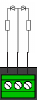
|
2
|
8x two-light signal
with fade effect
|
8
|
1
|
2
|
3
|
4
|
5
|
6
|
7
|
8
|

|
3
|
8x AHOB
|
8
|
1
|
2
|
3
|
4
|
5
|
6
|
7
|
8
|

|
4
|
2 groups with 8x
Fluorescent lamp
|
2
|
1
|
2
|

|
5
|
1 x 16 output with
Fluorescent lamp
|
1
|
1
|
|
6
|
8x Turnout motor
control
|
8
|
1
|
2
|
3
|
4
|
5
|
6
|
7
|
8
|

|
7
|
4x Dutch
three-light
signal
(CV131-134: 1)
|
4
|
1
|
2
|
3
|
4
|
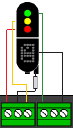
|
8
|
4x DB
Main signal
(CV131-134: 2)
|
4
|
1
|
2
|
3
|
4
|
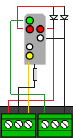
|
9
|
4x DB pre-signal
associated with main signal
(CV131-134: 3)
|
4
|
1
|
2
|
3
|
4
|
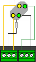
|
10
|
2x Combination of DB
Main signal and pre-signal
|
4
|
1
|
2
|
3
|
4
|
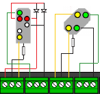
|
11
|
4x DB Pre-signal
(CV131-134: 4)
|
4
|
1
|
2
|
3
|
4
|
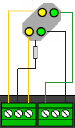
|
12
|
4x NMBS
Main signal
(CV131-134: 5)
|
4
|
1
|
2
|
3
|
4
|
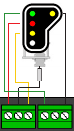
|
13
|
8x Turnout control
with time limit
|
8
|
1
|
2
|
3
|
4
|
5
|
6
|
7
|
8
|

|
|
0-13
|
n/a
|
|
|
107
|
|
Dark time between signal
transitions
|
|
1-255
|
70
|
|
108
|
|
Value to dim intensity of
signal (night mode)
|
|
0-15
|
10
|
|
109
|
|
PWM Period
|
The resolution with which the
internal PWM operates to achieve effects and dim -values
|
1-255
|
14
|
|
111
|
|
Fade Speed
|
The speed with which the
outputs configured for fading will fade in and fade out (bit
4 in output configuration CV113-128)
|
1-255
|
3
|
|
112
|
|
Blink rate
|
The speed with which the
outputs configured for blinking will blink (bit 5 in output
configuration CV113-128) |
1-255
|
183
|
output
configuration
|
1
|
113
|
|
Output Configuration 1
|
bit
|
function
|
|
default
|
value
|
0-3
|
Intensity of the
output.
|
Also called dimmer.
Where 0 is completely off and 15 completely on.
|
15
|
0-15
|
4
|
Fade in and fade out
effect.
|
- "0" = no fading
- "1" = fading active.
Fade speed is controlled by CV111
|
0
|
16
|
5
|
Blink effect
|
- "0" = no blinking
- "1" = blinking active.
Blink rate iscontrolled by CV112
|
0
|
32
|
6
|
Random effect
|
- "0" = random off
- "1" = random active.
Combined with bit 4 (fade) the lights start with a
flash, after which they slowly fade
in. Note: The intensity value should be max. 14 for
this effect to work.
|
0
|
64
|
7
|
Pulse
|
Length is set via CV
238 through 253, when combined with
bit 5 the output blinks, but with inverted phase
|
1
|
128
|
|
0-255
|
143
(b1000 1111)
|
2
|
114
|
|
Output Configuration 2
|
|
|
3
|
115
|
|
Output Configuration 3
|
|
|
4
|
116
|
|
Output Configuration 4
|
|
|
5
|
117
|
|
Output Configuration 5
|
|
|
6
|
118
|
|
Output Configuration 6
|
|
|
7
|
119
|
|
Output Configuration 7
|
|
|
8
|
120
|
|
Output Configuration 8
|
|
|
9
|
121
|
|
Output Configuration 9
|
|
|
10
|
122
|
|
Output Configuration 10
|
|
|
11
|
123
|
|
Output Configuration 11
|
|
|
12
|
124
|
|
Output Configuration 12
|
|
|
13
|
125
|
|
Output Configuration 13
|
|
|
14
|
126
|
|
Output Configuration 14
|
|
|
15
|
127
|
|
Output Configuration 15
|
|
|
16
|
128
|
|
Output Configuration 16
|
|
|
Signal
|
1
|
131
|
|
Type of signal #1 (linked
group of 4 outputs is specified in CV143)
|
If
the CV contains a value different than 0 all its controlled
outputs will switch according to the signal rules. The other
CVs that normally control the outputs will be deactivated.
value
->
|
0
|
1 |
2 |
3 |
4 |
5 |
used
by preset (CV47)
->
|
|
7
|
8
|
9
|
11
|
12
|
function
->
|
No Signal |
Dutch (NS railways)
(3-aspect + digit board) |
DB_HP (German main
signal) |
DB_VRHP (German front
and main signal) |
DB_VR (German front
signal) |
NMBS (Belgium
railways) |
address
|
|
|
|
|
|
|
1st
|
2nd
|
3rd
|
4th
|
|
|
|
|
|
|
R
|
R
|
R
|
night
dimming
|
|
Red
|
HP0
|
Off
|
VR0
|
Red
|
G
|
R
|
R
|
|
Green
|
HP1
|
VR0
|
VR1
|
Flashing red
|
R
|
G
|
R
|
|
Yellow
|
HP2
|
VR0
|
VR2
|
Double yellow
|
G
|
G
|
R
|
|
Flashing green with
digit
|
SH1
|
Off
|
Off
|
Flash double yellow
|
R
|
R
|
G
|
|
Yellow with digit
|
HP1
|
VR1
|
VR0
|
Green yellow horiz.
|
G
|
R
|
G
|
|
Flashing green
|
HP2
|
VR1
|
VR1
|
Green
|
R
|
G
|
G
|
|
Flashing yellow
|
HP1
|
VR2
|
VR2
|
Flashing green
|
G
|
G
|
G
|
|
Yellow with flashing
digit
|
HP2
|
VR2
|
Off
|
Green yellow vertical
|
|
0-5
|
0
|
2
|
132
|
|
Type of signal #2 (linked
group of 4 outputs is specified in CV167) |
3
|
133
|
|
Type of signal #3 (linked
group of 4 outputs is specified in CV191) |
4
|
134
|
|
Type of signal #4 (linked
group of 4 outputs is specified in CV215) |
Switching function keys in
control unit
(see table in p16 in pdf)
(see address-output)
|
|
group A (1-8)
|
group B
(9-16)
|
|
|
outputs group A (1-8) and group B (9-16)
|
|
1 | 9
|
2 | 10
|
3 | 11
|
4 | 12
|
5 | 13
|
6 | 14
|
7 | 15
|
6 | 16
|
value:
|
1
|
2
|
4
|
8
|
16
|
32
|
64
|
128
|
|
|
|
| 1st
address (Function Key 1) |
ON
|
141
|
142
|
|
- value contained in CV141 specifies which outputs
in group A are
activated when key 1 is pressed ON.
- value contained in CV142 specifies which outputs
in group B are
activated when key 1 is pressed ON.
- E.g.:
- to activate outputs 2 and 5 when key 1 is ON:
|
|
|
OFF
|
144
|
145
|
|
|
|
|
2nd
address (Function Key 2)
|
ON |
147
|
148
|
|
|
|
|
| OFF |
150
|
151
|
|
|
|
|
3rd
address (Function Key 3)
|
ON |
153
|
154
|
|
|
|
|
| OFF |
156
|
157
|
|
|
|
|
4th
addresss (Function Key) 4
|
ON |
159
|
160
|
|
|
|
|
| OFF |
162
|
163
|
|
|
|
|
5th
address (Function Key 5)
|
ON |
165
|
166
|
|
|
|
|
| OFF |
168
|
169
|
|
|
|
|
6th
address (Function Key 6)
|
ON |
171
|
172
|
|
|
|
|
| OFF |
174
|
175
|
|
|
|
|
7th
address (Function Key 7)
|
ON |
177
|
178
|
|
|
|
|
| OFF |
180
|
181
|
|
|
|
|
8th
address (Function Key 8)
|
ON |
183
|
184
|
|
|
|
|
| OFF |
186
|
187
|
|
|
|
|
9th
address (Function Key 9)
|
ON |
189
|
190
|
|
|
|
|
| OFF |
192
|
193
|
|
|
|
|
10th
address (Function Key 10)
|
ON |
195
|
196
|
|
- value contained in CV195 specifies which outputs in
group A are activated when key 10 is pressed ON.
- value contained in CV196 specifies which outputs in
group B are activated when key 10 is pressed ON.
- E.g.:
- to activate outputs 1 and 15 when key 10 is ON:
- set CV195 to 1
- set CV196 to 64
|
|
|
| OFF |
198
|
199
|
|
|
|
|
11th
address (Function Key 11)
|
ON |
201
|
202
|
|
|
|
|
| OFF |
204
|
205
|
|
|
|
|
12th
address (Function Key 12)
|
ON |
207
|
208
|
|
|
|
|
| OFF |
210
|
211
|
|
|
|
|
13th
address (Function Key 13)
|
ON |
213
|
214
|
|
|
|
|
| OFF |
216
|
217
|
|
|
|
|
14th
address (Function Key 14)
|
ON |
219
|
220
|
|
|
|
|
| OFF |
222
|
223
|
|
|
|
|
15th
address (Function Key 15)
|
ON |
225
|
226
|
|
|
|
|
| OFF |
228
|
229
|
|
|
|
|
16th
address (Function Key 16)
|
ON |
231
|
232
|
|
|
|
|
| OFF |
234
|
235
|
|
|
|
|
SIGNAL
|
1
|
143
|
|
Group of outputs coupled to
SIGNAL 1
|
|
outputs
|
|
1-4
|
5-8
|
9-12
|
13-16
|
value:
|
1
|
2
|
4
|
8
|
|
|
1
|
2
|
167
|
|
Group of outputs coupled to
SIGNAL 2
|
|
2
|
3
|
191
|
|
Group of outputs coupled to
SIGNAL 3
|
|
4
|
4
|
215
|
|
Group of outputs coupled to
SIGNAL 4
|
|
8
|
Pulse
time
for OUTPUT ...
|
1
|
238
|
|
Pulse time OUTPUT 1
|
bit 7
in output 1 configuration (CV113)
|
|
|
2
|
239
|
|
Pulse time OUTPUT 2
|
bit 7 in output 2
configuration (CV114) |
|
|
3
|
240
|
|
Pulse time OUTPUT 3
|
bit 7 in output 3
configuration (CV115) |
|
|
4
|
241
|
|
Pulse time OUTPUT 4
|
bit 7 in output 4
configuration (CV116) |
|
|
5
|
242
|
|
Pulse time OUTPUT 5
|
bit 7 in output 5
configuration (CV117) |
|
|
6
|
243
|
|
Pulse time OUTPUT 6
|
bit 7 in output 6
configuration (CV118) |
|
|
7
|
244
|
|
Pulse time OUTPUT 7
|
bit 7 in output 7
configuration (CV119) |
|
|
8
|
245
|
|
Pulse time OUTPUT 8
|
bit 7 in output 8
configuration (CV120) |
|
|
9
|
246
|
|
Pulse time OUTPUT 9
|
bit 7 in output 9
configuration (CV121) |
|
|
10
|
247
|
|
Pulse time OUTPUT 10
|
bit 7 in output
10 configuration (CV122) |
|
|
11
|
248
|
|
Pulse time OUTPUT 11
|
bit 7 in output
11 configuration (CV123) |
|
|
12
|
249
|
|
Pulse time OUTPUT 12
|
bit 7 in output
12 configuration (CV124) |
|
|
13
|
250
|
|
Pulse time OUTPUT 13
|
bit 7 in output
13 configuration (CV125) |
|
|
14
|
251
|
|
Pulse time OUTPUT 14
|
bit 7 in output
14 configuration (CV126) |
|
|
15
|
252
|
|
Pulse time OUTPUT 15
|
bit 7 in output
15 configuration (CV127) |
|
|
16
|
253
|
|
Pulse time OUTPUT 16
|
bit 7 in output 16
configuration (CV128) |
|
|
Primary
address (first accessory address)
|
|
513
|
|
Primary
Address (start address) (first accessory address LSB)
Low
|
| CV521 |
CV513 |
first accessory address = CV521*256 + CV513 + 1 |
| 0 |
0 |
1 |
| 0 |
1 |
2 |
| 0 |
2 |
3 |
| 0 |
3 |
4 |
| 0 |
4 |
5 (?default; after reset by sending CV8=8) |
| ... |
|
|
| 0 |
255 |
256 |
| 1 |
0 |
257 |
| 1 |
1 |
258 |
| ... |
|
|
| 7 |
254 |
2047 |
| 7 |
255 |
2048 |
|
|
4
|
|
521
|
|
Primary
Address (start address) (first accessory address MSB)
High
|
|
0
|
|
|
|
|
group A |
|
group B
|
|
|
output → |
|
1
|
2
|
3
|
4
|
5
|
6
|
7
|
8
|
|
9
|
10
|
11
|
12
|
13
|
14
|
15
|
16
|
|
|
CV for output configuration →
|
|
113
|
114
|
115
|
116
|
117
|
118
|
119
|
120
|
|
121
|
122
|
123
|
124
|
125
|
126
|
127
|
128
|
|
|
value →
|
|
1
|
2
|
4
|
8
|
16
|
32
|
64
|
128
|
|
1
|
2
|
4
|
8
|
16
|
32
|
64
|
128
|
Address
/ Key
|
|
|
CV ↓
|
|
|
|
|
|
|
|
|
CV ↓ |
|
|
|
|
|
|
|
|
1st Address / key
|
on (1)
|
|
141
|
|
|
|
|
|
|
|
|
142
|
|
|
|
|
|
|
|
|
off (0)
|
|
144
|
|
|
|
|
|
|
|
|
145
|
|
|
|
|
|
|
|
|
2nd
Address / key
|
on (1) |
|
147
|
|
|
|
|
|
|
|
|
148
|
|
|
|
|
|
|
|
|
| off (0) |
|
150
|
|
|
|
|
|
|
|
|
151
|
|
|
|
|
|
|
|
|
3rd
Address / key
|
on (1) |
|
153
|
|
|
|
|
|
|
|
|
154
|
|
|
|
|
|
|
|
|
| off (0) |
|
156
|
|
|
|
|
|
|
|
|
157
|
|
|
|
|
|
|
|
|
4th
Address / key
|
on (1) |
|
159
|
|
|
|
|
|
|
|
|
160
|
|
|
|
|
|
|
|
|
| off (0) |
|
162
|
|
|
|
|
|
|
|
|
163
|
|
|
|
|
|
|
|
|
5th
Address / key
|
on (1) |
|
165
|
|
|
|
|
|
|
|
|
166
|
|
|
|
|
|
|
|
|
| off (0) |
|
168
|
|
|
|
|
|
|
|
|
169
|
|
|
|
|
|
|
|
|
6th
Address / key
|
on (1) |
|
171
|
|
|
|
|
|
|
|
|
172
|
|
|
|
|
|
|
|
|
| off (0) |
|
174
|
|
|
|
|
|
|
|
|
175
|
|
|
|
|
|
|
|
|
7th
Address / key
|
on (1) |
|
177
|
|
|
|
|
|
|
|
|
178
|
|
|
|
|
|
|
|
|
| off (0) |
|
180
|
|
|
|
|
|
|
|
|
181
|
|
|
|
|
|
|
|
|
8th
Address / key
|
on (1) |
|
183
|
|
|
|
|
|
|
|
|
184
|
|
|
|
|
|
|
|
|
| off (0) |
|
186
|
|
|
|
|
|
|
|
|
187
|
|
|
|
|
|
|
|
|
9th
Address / key
|
on (1) |
|
189
|
|
|
x
|
|
|
|
|
|
190
|
|
|
|
|
|
|
|
|
| off (0) |
|
192
|
|
|
|
x
|
|
|
|
|
193
|
|
|
|
|
|
|
|
|
10th
Address / key
|
on (1) |
|
195
|
|
|
|
|
|
|
|
|
196
|
|
|
|
|
|
|
|
|
| off (0) |
|
198
|
|
|
|
|
|
|
|
|
199
|
|
|
|
|
|
|
|
|
11th
Address / key
|
on (1) |
|
201
|
|
|
|
|
|
|
|
|
202
|
|
|
|
|
|
|
|
|
| off (0) |
|
204
|
|
|
|
|
|
|
|
|
205
|
|
|
|
|
|
|
|
|
12th
Address / key
|
on (1) |
|
207
|
|
|
|
|
|
|
|
|
208
|
|
|
|
|
|
|
|
|
| off (0) |
|
210
|
|
|
|
|
|
|
|
|
211
|
|
|
|
|
|
|
|
|
13th
Address / key
|
on (1) |
|
213
|
|
|
|
|
|
|
|
|
214
|
|
|
|
|
|
|
|
|
| off (0) |
|
216
|
|
|
|
|
|
|
|
|
217
|
|
|
|
|
|
|
|
|
14th
Address / key
|
on (1) |
|
219
|
|
|
|
|
|
|
|
|
220
|
|
|
|
|
|
|
|
|
| off (0) |
|
222
|
|
|
|
|
|
|
|
|
223
|
|
|
|
|
|
|
|
|
15th
Address / key
|
on (1) |
|
225
|
|
|
|
|
|
|
|
|
226
|
x
|
x
|
|
|
|
|
|
|
| off (0) |
|
228
|
|
|
|
|
|
|
|
|
229
|
|
|
x
|
|
|
|
|
|
16th
Address / key
|
on (1) |
|
231
|
|
|
|
|
|
|
|
|
232
|
|
|
|
|
|
|
|
|
| off (0) |
|
234
|
|
|
|
|
|
|
|
|
235
|
|
|
|
|
|
|
|
|
- Examples
- when address/key #9 is on/green, move a turnout (connected
to outputs 3,C,4) to right position; when address/key #9 is
off/red move it to turn position
- key #9
- on: set CV189 to 4 (activate output 3)
- off: set CV192 to 8 (activate output 4)
- outputs:
- output 3: set CV115 to 10001111=143 (pulse,
highest intensity)
- output 4: set CV116 to 10001111=143 (pulse,
highest intensity)
- when address/key #15 is on/green, activate a solid green
led connected to output 9 and a blinking yellow led
connected to output 10; when off, activate a solid red led,
connected to output 11:
- key #15
- on: set CV226 to 1+2=3
- off: set CV229 to 4
- outputs:
- output 9 (green led): set CV121 to 00011111=31
(fade,highest intensity)
- output 10 (yellow led): set CV122 to 00111111=63
(blinking,fade,highest intensity)
- output 11 (red led): set CV123 to 00011111=31
(fade,highest intensity)
|
|
|
...
- Variants:
- DR4088RB (R-BUS)
- Identical to Roco
10787 (pdf)
- Setup start address
- Notes:
- PAY ATTENTION! According to the R-BUS standard is
mandatory to always start at address 1. You can
not choose any address.
- Important! The DR4088RB feedbacks are equipped
with 16 feedback points. This means
that each module uses two addresses. A second
DR4088RB feedback unit must begin
with address 3.
- Steps using "Z21
Maintenance Tool"
- Connect DR4088RB feedback unit as the only
feedback module to the central z21 use hard
del a Loconet or R BUS cable.
- Open "Z21 Maintenance Tool" (Android app)
- Go to the "R-BUS" and enter in Module address tab
in the number 1.
- Press the 'Assign' button in the "Z21 Maintenance
Tool" application.
- The application now asks to disconnect the
feedback module.
Disconnect the DR4088RB NOT from the z21 in this
case! But once the pressure
Program Button on the DR4088RB. The green LED
briefly pulsate.
- Press OK
- Then the next screen where you press OK.
- The DR4088RB feedback has received the address and
stored.
The green LED flashes again in normal mode.
- The module give an address
In the following order, you can DR4088RB feedback module
includes a start address.
PAY ATTENTION! According to the R-BUSTM standard is
mandatory to always start at address 1. You can
not choose any address.
Important! The DR4088RB feedbacks are equipped with 16
feedback points. This means
that each module uses two addresses. A second DR4088RB
feedback unit must begin
with address 3.
1. Connect DR4088RB feedback unit as the only feedback
module to the central z21TM use hard
del a LoconetTM or R BUSTM cable.
2. Open Z21TM Maintenance Tool
3. Go to the "R-BUS" and enter in Module address tab in the
number 1.
4. Press the 'Assign' button in the Z21TM Maintenance Tool
application.
5. The application now asks to disconnect the feedback
module.
Disconnect the DR4088RB NOT from the z21 in this case! But
once the pressure
Program Button on the DR4088RB. The green LED briefly
pulsate.
5. Press OK
6. Then the next screen where you press OK.
7. The DR4088RB feedback has received the address and
stored.
The green LED flashes again in normal mode.
|
|
|
- Z21
signal DECODER (10837)
- Assignment (Appendix A - Signal configuration "Universal")
-
| terminal |
assignment
(LED) |
note |
| 1 |
red |
red light for stop |
| 2 |
red |
second red stop |
| 3 |
green |
green light for proceed |
| 4 |
yellow
orange |
yellow light for proceed with speed limit |
| 5 |
white
orange |
additional lamps for cancellation of the movement
or shunting prohibited |
| 6 |
white |
possibility for the connection of a speed or
direction display |
| 7 |
green |
second green light |
| 8 |
reserved |
|
- Signal aspects (vegeu/see: Senyalització / Signalling) (Appendix A -
Signal configuration "Universal")
-
| No. |
DCC
ext |
DCC
basic
(G=straight;
R=branch) |
Name |
Description |
proposal
for ADIF |
|
0 |
1R |
Stop |
Absolute stop |
FF7 |
|
4 |
2G |
Go 40 |
Proceed with limit 40 km/h |
FF3 |
|
6 |
3R |
Go 60 |
Proceed with limit 60 km/h |
|
|
16 |
1G |
Go |
Clear |
FF1A |
|
65 |
2R |
Shunt go |
Shunting allowed |
FF8 |
|
66 |
|
|
Dark switching (e.g. light distant signals) |
|
|
68 |
4R |
Warning |
|
|
|
69 |
3G |
Substitution |
Substitution signal (permits trains to pass) |
|
|
70 |
4G |
Blink |
|
|
- CV
-
| CV |
description |
range |
default |
| #1 |
First decoder address |
|
|
| #7 |
Manufacturer firmware version number |
|
|
| #8 |
Manufacturer identification |
|
|
| #9 |
Decoder address |
0-7 (read only) |
|
| #28 |
RailCom configuration |
|
|
| #29 |
Decoder configuration |
|
|
| #39 |
DCC addressing mode |
|
|
| #40 |
Number of signals |
2,3,4 |
2 |
| #41 |
Signal-ID for signal 1 |
0-255
| value |
hex |
name (Appendix B - Signal configurations) |
| 64 |
0x40 |
4 single LEDs |
| 65 |
0x41 |
4 fading LEDs |
| 67 |
0x43 |
4 running lights |
| 71 |
0x47 |
Universal |
| 72 |
0x48 |
Universal #2 (red flashing for
Substitution) |
| 73 |
0x49 |
Railway crossing |
| 77 |
0x4d |
Roco 10777 |
| 160-170 |
0xa. |
(AT) ÖBB |
| 176-177 |
0xb. |
NS |
| 192-205 |
0xc. |
(CH) SBB |
| 208-221 |
0xd. |
(DE) DB |
|
0xe. |
(ES) ADIF |
| 240-244 |
0xf. |
(FR) SNCF |
|
71 (Universal) |
| #42 |
Signal-ID for signal 2 |
| #43 |
Signal-ID for signal 3 |
| #44 |
Signal-ID for signal 4 |
| #45 |
Initialisation signal 1 |
0-255 |
255 |
| #46 |
Initialisation signal 2 |
| #47 |
Initialisation signal 3 |
| #48 |
Initialisation signal 4 |
| #61 |
Current DCCext value of signal 1 |
|
|
| #62 |
Current DCCext value of signal 2 |
|
| #63 |
Current DCCext value of signal 3 |
|
| #64 |
Current DCCext value of signal 4 |
|
| #65 |
Current number of the signal aspect from signal 1 |
|
|
| #66 |
Current number of the signal aspect from signal 2 |
|
| #67 |
Current number of the signal aspect from signal 3 |
|
| #68 |
Current number of the signal aspect from signal 4 |
|
| #211 |
DCCbasic / DCCext mapping for Signal 1, 1R |
0..254: explicit
specification through user
255: specification in accordance with signal
configuration |
255 |
| #212 |
DCCbasic / DCCext mapping for Signal 1, 1G |
| #213 |
DCCbasic / DCCext mapping for Signal 1, 2R |
| #214 |
DCCbasic / DCCext mapping for Signal 1, 2G |
| #221-#224 |
DCCbasic / DCCext mapping for Signal 2 |
| #231-#234 |
DCCbasic / DCCext mapping for Signal 3 |
| #241-#244 |
DCCbasic / DCCext mapping for Signal 4 |
| #250 |
Decoder type (37 = ROCO 10387 Z21 signal DECODER) |
read only |
37 |
|
|
|
- Config
- YD9100
(USB)
ID 0403:6015 Future Technology Devices
International, Ltd Bridge(I2C/SPI/UART/FIFO)- YD-Command
- Linux (wine32)
- Instal·lació / Installation
- Comunicació
sèrie / Serial communication
- Execució / Run
cd ~/.toto_win_32/drive_c/YaMoRC/YaMoRC
                                  Configuration and Drivers/Config
WINEPREFIX=~/.toto_win_32 WINEARCH=win32
wine YD9100.exe
|
|
http://www.francescpinyol.cat/.html
Primera versió: / First version: 9.V.2015
Darrera modificació: 24 d'agost de 2024 / Last update: 24th August
2024

Cap a casa / Back home. |
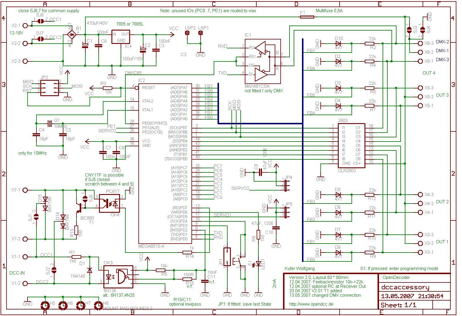
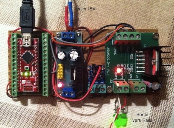